UDM35HSXSXR2LTX中文资料

?Multi-input modular instrument 3 1/2 dgt LED ?0.1% RDG basic accuracy
?TRMS AC current and voltage measurements
?AC/DC current measurements: selectable full scales (200μA to 5A)
?AC/DC voltage measurements: selectable full scales (200mV to 500V)
?°C or °F temperature measurements
(Pt100-250-500-1000, Ni100, TC J-K-S-T -E)
?Resistance measurements: selectable full scales (20?to 20k ?)
?Up to 4 independent alarm set-points (optional)?20mA/10VDC analog output (optional)?Serial port RS485 or RS232 (optional)
?
MODBUS, JBUS communication protocol
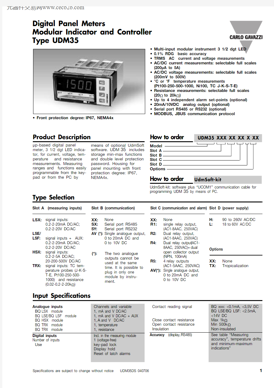
Product Description
μp-based digital panel meter, 3 1/2 dgt LED indica-tor, for current, voltage, tem-perature and resistance measurements. Measuring ranges and functions easily programmable from the key-pad or from the PC by
means of optional UdmSoft software. UDM 35includes storage min-max functions and double level protection password. Housing for panel mounting with front protection degree: IP67,NEMA4x.
Type UDM35
Type Selection
Slot A (measuring inputs)LSX:signal inputs:
0.2-2-20mA DC/AC;0.2-2-20V DC/AC
LSE/
LSF:signal inputs + AUX:
0.2-2-20mA DC/AC;0.2-2-20V DC/AC
HSX:signal inputs:
0.2-2-5A DC/AC; 20-200-500V DC/AC
TRX:signal inputs: TC tem-perature probes (J-K-S-T-E, Pt100-250-500-1000) and resistance (0.02-0.2-2-20k ?)
Slot B (communication)XX:None
SX:Serial port RS485SY:Serial port RS232AV (*):
Single analogue output, 0to 20mA DC and 0to 10V DC Slot D (power supply)H:90 to 260V AC/DC L:
18to 60V AC/DC
Options XX:None
TX:
Tropicalization
Input Specifications
?Front protection degree:IP67, NEMA4x
UdmSoft-kit: software plus “UCOM1” communication cable for programming UDM 35by means of PC.
Modular Indicator and Controller Digital Panel Meters
Slot C (communication and alarm)XX:None
R1:
single relay output,(AC1-8AAC, 250VAC)
R2:Dual relay output,
(AC1-8AAC, 250VAC)
R4:Dual relay output (AC1-8AAC, 250VAC) +dual
open collector output (NPN, 100mA)
R5:4relay outputs
(AC1-5AAC, 250VAC)
AV(*):Single analogue output,
0to 20mA DC and 0to 10V DC
(*):
The two analogue outputs cannot be used at the same time. It is possible to plug in only one module by instru-ment.
Measurement accuracy, temperature drifts, max and min indications
All accuracies and min/max indications are referred to an ambient temperature range of 25°C±5°C, relevant humidity ≤60% and scale ratio (electrical/displayed scale) equal to 1. The conversion into °F is obtained acting on the electrical/displayed scale ratio. Array *<45Hz >65Hz= ±(0.5%RDG+3DGT) 0% to 25% FS;±(0.5%RDG+2DGT) 25% to 110% FS.
( )The min. indication for TRMS measurement (AC or DC) is 0; it is possible to modify the decimal point position.
All accuracies and min/max indications refer to an ambient temperature range of 25°C ±5°C, relevant humidity ≤60% and scale ratio (elec-trical scale / displayed scale) equal to 1. The conversion into °F is obtained acting on the electrical scale / displayed scale .
Input impedances and overloads
UDM35
Output specifications
UDM35
Software functions
General Specifications
UDM35
AC/DC voltage
90 to 260V (standard)18 to 60V (on request)
Energy consumption
≤30VA/12W (90 to 260V)≤20VA/12W (18 to 60V)
Supply Specifications
Available modules
Only for TRMS Measurements Instantaneous effective voltage (TRMS)
?
×=
n
i V n
V 1
2
11)(1?×=
n
i A n A 1
211)(1
Used calculation formulas
Instantaneous effective current (TRMS)
Insulation between inputs and outputs
Excitation output Possible module combinations
(*) Up to 1 module max.
UDM35
Wiring diagrams
Process signal wiring diagrams
Wirings for high-level signals
UDM35
Wiring diagrams of optional modules
BO R1: 1 relay output
BO R2: 2 relay outputs BO AV: analogue output (10V
, 20mA DC)
Wiring diagrams for temperature measurements Wiring diagrams (cont.)
Wiring diagrams for power supply
BO R5: 4 relay outputs
UDM35
BO R4: dual relay output + dual open collector output: the load resistances (Rc) must be designed so that the close contact current is lower than 100mA; the VDC voltage must be lower than or equal to 30VDC.VDC: power supply output
Vo+: positive output (open collector transistor).
GND: ground collector (open collector transistor).
BR SX: RS485 4-wire connection:additional devices provided with RS485 port (indicated as RS1,2,3...N) are connected in parallel. The termination of the serial port is carried out only on the last instrument of the network. The serial module is provided with a jumper for the termination of the RS485 network as shown in the figure above.
Note:particular types of cables or plants may require an external termination. For the network connections use twisted cable type AWG26.
RS1,2,3...N
Programming UDM35 by means of PC
Wiring diagrams of optional modules (cont.)
UDM35 is programmable by PC by means of the UdmSoft software (available on request). The user can program all parameters of UDM35 that will be subse-quently uploaded and set in the instrument by the RS485 network (BRSX).
Should UDM35 be without the RS485 serial module, all programming parameters will be uploaded and set in the instrument by the RS232 auxiliary serial connec-tion (1) located on the side of the measuring input module using the special con-nection cable (2) available on request, as shown in the figures on the left. It is also possible to program the instrument using the dot connector (1) by means of the HyperTerminal Windows functions of a PC.
Note:the RS232 auxiliary port IS NOT insulated from the measuring inputs.
Ordering code of the cable (2): UCOM1
BO SY: RS232 direct
connection to PC by means of COM port.RS232 has no termi-nalization.
UDM35
Dimensions
Front panel description
1.Key-pad
The programming of the configuration parameters and the display may be easily controlled by means of the 4 function :to enter the programming phase and to confirm the Engineering Units
UDM35
BP L
Power supply:
18 to 60V AC/DC
BO R4
Dual relay output +
Dual open collector
BO R2
Dual relay output
BO AV
Single analogue
output 10V , 20mA DC
BQ LSX, BQ LSE, BQ LSF , BQ HSX, BQ TRX Measuring inputs Input modules
Serial port modules BR SX
RS485 Serial port BP H
Power supply: 60 to 260V AC/DC
Modules
BO R1
Single relay output
Output modules
Scale 1:1
Power supply modules
Output modules
BO R5
4
relay outputs
BR SY
RS232 Serial port