EN 1994-Eurocade 4 Design of composite steel and concrete structures

EN 1994 - Eurocode 4: Design of composite steel and concrete
structures
Composite slabs
Stephen Hicks BEng(Hons), PhD(Cantab.)
Senior Manager Building Engineering
The Steel Construction Institute
Silwood Park
Ascot, Berkshire, SL5 7QN
United Kingdom
Telephone: +44 (0)1344 636540, Fax: +44 (0)1344 636570
E-mail:s.hicks@https://www.wendangku.net/doc/273393907.html,
INTRODUCTION
Composite construction has proved popular over the last twenty years, and has largely accounted for the dominance of steel frames in multi-storey buildings within the UK. The main benefits in using composite beams are that:
?Savings in steel weight of between 30 to 50% can be achieved compared to non-composite beams.
?The increased stiffness of composite beams can result in them being shallower than non-composite beams for the same span; this can lead to lower storey heights and a reduction to cladding costs (which is significant, as cladding can represent up to 20% of the total building cost[1]), or allowing more room for mechanical services. The cold formed profiled steel sheeting is an integral part of the structural system as it performs the following roles:
?It acts as a safe working platform and protects the workers below.
?It supports the loads during construction and may eliminate the need for temporary propping.
?It acts as permanent formwork for the concrete slab.
? Through mechanical or frictional interlock (and/or the provision of end anchorage), composite action can develop with the concrete such that the sheet provides all, or part, of the main tension reinforcement to the slab.
? Through the provision of through-deck welded stud shear connectors, the composite slab may be used to provide restraint to the steel beams.
TYPES OF PROFILED STEEL SHEET
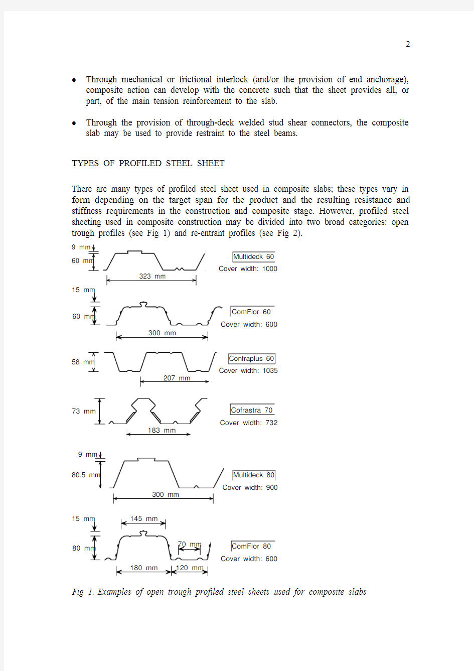
There are many types of profiled steel sheet used in composite slabs; these types vary in form depending on the target span for the product and the resulting resistance and stiffness requirements in the construction and composite stage. However, profiled steel sheeting used in composite construction may be divided into two broad categories: open
trough profiles (see Fig 1) and re-entrant profiles (see Fig 2).
Cover width: 1000
Multideck 60
ComFlor 60
Confraplus 60Cover width: 1035
Cofrastra 70
Cover width: 732
Cover width: 900Multideck 80
ComFlor 80Cover width: 600
Fig 1. Examples of open trough profiled steel sheets used for composite slabs
To resist the loads and provide sufficient stiffness at the construction stage, the cross-section of the sheet may be designed using the equations given in EN 1993-1-3; in spite of this, it is more common for the manufacturer to publish design properties that have been evaluated from the test procedures given in Annex A of this Eurocode. The benefit of using design properties evaluated from tests is that greater spanning capabilities may be achieved (typically, spans of between 10 to 15% in excess of those predicted by the design equations given in EN 1993-1-3 may be possible).
The rules in EN 1994-1-1 are only appropriate for profiled steel sheeting thicknesses above a certain value; although the minimum nominal thickness may be given in the National Annex, the recommended value is t ≥ 0,70 mm. Typically, profiled steel sheeting is galvanized for durability purposes. In these situations care should be taken on the thickness that is used in design owing to the fact that the sheet thickness that is often quoted by manufacturers is the overall thickness, including the galvanized coating, rather than the core or ‘bare metal’ thickness which should be used in structural calculations. For example, for a coating of 275 g/m3, the core thickness is approximately 0,04 mm smaller than the overall thickness of the sheet.
The application of EN 1994-1-1 is limited to sheets with narrowly spaced webs, which are defined by the ratio of the width of the sheet rib to the rib spacing b r / b s ; although the upper limit may be given in the National Annex, the recommended value is b r / b s ≤ 0,6.
TYPES OF SHEAR CONNECTION
To enable composite action to be assumed between the profiled steel sheet and the concrete, the longitudinal shear force should be transferred by the sheet by the following forms of connection:
a) Mechanical interlock through the provision of indentations or embossments rolled into the profile (see Fig 3(a)).
b) Frictional interlock for re-entrant profiles (see Fig 3(b)).
Cover width: 750Cofrastra 40
152.5 mm Cover width : 610Super Holorib 51
Fig 2. Examples of re-entrant profiled steel sheets used for composite slabs
(a)(c)
(b)(d)
Fig 3.Typical forms of shear connection in composite slabs
According to EN 1994-1-1, it is not permitted to rely on pure bond between the steel sheet and the concrete; the differentiation between pure bond and frictional interlock is that frictional interlock is what remains after a composite slab is subjected to 5000 cycles of load in a standard test. For cases when the mechanical or frictional interlock is not sufficient, the shear connection may be augmented by providing anchorage at the end of the sheet from:
c)Through-deck welded stud connectors, or any other local connection between the
steel sheet and the concrete (see Fig 3(c)).
d)Deformation of the ends of the ribs at the end of the sheeting (see Fig 3(d)).
The most common way of providing anchorage to a sheet is from through-deck welded stud connectors; however, it should be noted that the safe span tables published by the manufacturers often do not include this beneficial effect, owing to the fact that the sheeting can sometimes be bearing on masonry walls.
DETAILING PROVISIONS
Based on the satisfactory performance of floors that had previously been constructed in a wide range of countries, EN 1994-1-1 species the following minimum slab thicknesses that should be used in design:
?Where the slab acts compositely with a beam, or is used as a diaphragm:
o the overall depth of the slab h≥ 90 mm; and
o the thickness of concrete above the main flat surface of the top of the ribs of the sheeting h c≥ 50 mm.
? Where the slab does not act compositely with a beam, or has no other stabilising function:
o the overall depth of the slab h ≥ 80 mm; and
o the thickness of concrete above the main flat surface of the top of the ribs
of the sheeting h c ≥ 40 mm.
EN 1994-1-1 also specifies that the minimum amount of reinforcement in both directions should not be less than 80mm2/m (which is based on the smallest value of h c and the minimum percentage of crack-control reinforcement for unpropped construction). It is also specified that the spacing of the reinforcement bars should not exceed 2h or 350 mm, whichever is the lesser.
In addition to the above, the largest nominal aggregate size d g should satisfy the following:
?????≤mm 5,313
/4,00c g b h d (1)
The bearing length is the longitudinal length of sheeting or slab in direct contact with the support. In each case this length should be sufficient to satisfy the relevant criterion. For sheeting, it should be sufficient to avoid excessive rib deformations, or web failure, near the supports during construction. For the slab, it should be sufficient to achieve the required resistance of the composite slab. The recommended bearing lengths and support details differ depending upon the support material (steel, concrete, etc.), and they are different for interior and exterior supports. According to EN 1994-1-1, the bearing lengths l bc and l bs should not be less than the following (see Fig 4):
? for composite slabs bearing on steel or concrete: l bc = 75 mm and l bs = 50 mm; ? for composite slabs bearing on other materials: l bc = 100 mm and l bs = 70 mm.
Fig 4. Minimum bearing lengths
The detail in Fig 4(c) may not be practical, owing to the fact that through-deck welding of studs through two thicknesses of sheet is not recommended.
ACTIONS AND ACTION EFFECTS
PROFILED STEEL SHEETING
For both speed and simplicity of construction, unpropped construction is normally used for profiled steel sheeting (i.e. without temporary propping). For this type of construction the sheet thicknesses are normally between 0,86 and 1,16 mm and are provided in continuous two-span lengths to benefit from continuity over the central support. In this situation the spanning capability of the sheeting is normally dictated by resistance or deflection criteria at the construction condition.
The loading that should be considered in the design of the decking is given in EN 1991-1-6. For normal concrete, EN 1991-1-1 recommends that the density should be taken to be 24 kN/m3, increased by 1.0 kN/m3 for normal reinforcement and increased by a further 1.0 kN/m3 when the concrete is unhardened. As a consequence of this, the self weight load that should be considered in the construction condition corresponds to the design thickness of the slab with a normal concrete density of 26 kN/m3. An additional load from the increased depth of concrete arising from the deflection of the sheeting (known as ‘ponding’) should also be included. According to EN 1994-1-1, if the central deflection of the sheeting δ is greater than 1/10 of the slab thickness, ponding should be allowed for. In this situation the nominal thickness of the concrete over the complete span may be assumed to be increased by 0,7δ.
As well as the self weight of the fresh concrete, EN 1991-1-6 specifies an imposed load consisting of a moving 3 m × 3 m working area (or the length of the span if less), with an intensity of 10% of the self-weight of the concrete but ≤ 1,5kN/m2 and ≥ 0,75 kN/m; this load represents the concreting operation and heaping of concrete locally. Outside the working area, an imposed load of 0,75 kN/m2 should be applied to the profiled steel sheeting.
ANALYSIS FOR INTERNAL FORCES AND MOMENTS
PROFILED STEEL SHEETING
In the analysis of unpropped profiled steel sheeting, it is possible to permit the moment over the internal supports to be redistributed into the span at the ultimate limit state. For profiled steel sheeting that was common to the UK in the 1980’s, the amount of plastic redistribution that was assumed was between 5 and 10%[2]; however, greater values of redistribution are capable for some modern steel sheets and, in these situations, the
exact amount that may be assumed in design has been evaluated from tests according to EN 1993-1-1, Annex A.
The use of temporary props permits much longer spans and/or thinner sheets to be used. In this situation the spanning capability of the system is often dictated by the longitudinal shear resistance of the shear connection to the composite slab. However, unlike unpropped construction, EN 1994-1-1 does not permit plastic redistribution at the ultimate limit state when temporary supports are used.
COMPOSITE SLAB
According to EN 1994-1-1, the following methods of analysis may be used for composite slabs at the ultimate limit state:
a)Linear-elastic analysis with, or without redistribution.
b)Rigid plastic global analysis provided that it is shown that sections where plastic
rotations are required have sufficient rotation capacity.
c)Elastic-plastic analysis, taking into account the non-linear material properties.
As the sheeting is provided in two-span lengths, together with the fact that the concrete is cast on top of the sheets without joints, the composite slab is normally continuous (details on numerical and experimental results on continuous slabs are given in reference[3]). However, although the finished slab is continuous, it can sometimes be beneficial for designers to assume that it is simply-supported in normal conditions and use linear-elastic analysis. This design approach is often used in the UK, and the continuity that exists over the supports from the provision of nominal anti-crack reinforcement bars, together with any supplementary reinforcement, is only taken into account of in fire conditions[4].
VERIFICATION OF PROFILED STEEL SHEETING AS SHUTTERING
The design properties of the profiled steel sheeting should be evaluated using the design equations or tests according to EN 1993-1-3. For the ultimate limit state, the resistance of the sheet to sagging and hogging bending, together with the effects of combined bending and web crushing, are normally critical. For the serviceability limit state, although the limiting value of the deflection δs,max of steel sheeting under its own weight plus the weight of wet concrete may be given in the National Annex, the recommended value is L/180 (where L is the effective span between supports).
VERIFICATION OF COMPOSITE SLABS FOR ULTIMATE LIMIT STATES FLEXURE
The bending resistance of composite slabs may be calculated from EN1994-1-1 using the ‘partial connection’ or the ‘m-k’ method. Both methods rely on tests on composite slabs to evaluate the shear connection, or ‘shear bond’ value, for the variables under investigation. The tests consist of two groups of composite slabs subjected to two concentrated loads applied at a distance L s from the supports. For each variable investigated, the groups of composite slab specimens should include the following: ?Test specimens with the shear span L s as long as possible, whilst still providing failure in longitudinal shear.
?Test specimens with the shear span L s as short as possible (but not less than 3 × overall slab thickness), whilst still providing failure in longitudinal shear.
For the partial connection method, a minimum of four tests should be undertaken comprising three long specimens and one short specimen (to classify whether the behaviour is ductile or brittle). Conversely, for the m-k method, a minimum of six tests should be undertaken with three long specimens and three short specimens.
No guidance is given in EN 1994-1-1 on the minimum number of variables that should be investigated by tests; however, there is some evidence that the shear bond value is affected by slab thickness and it has been recommended[5] that, for a constant shear span, the thinnest and thickest slab depths should be investigated.
The test loading procedure is intended to represent that which would occur on the floor over a period of time. The initial test consists of subjecting the composite slab test to 5000 cycles of load to eliminate pure bond between the sheet and the concrete so that only the mechanical or frictional interlock remains; this is followed by a subsequent test, where the slab is progressively subjected to load until failure occurs. A typical example of a composite slab test under load is shown in Fig 5.
Fig 5.Typical composite floor slab test
The bending resistance design methodology for the composite slab is highly dependant on the behaviour of test specimens. For cases when the longitudinal shear behaviour may be considered as ductile, both the partial connection and m-k method may be used. However, if the behaviour is brittle, only the m-k method is permitted and a 20% penalty is applied to the test results. According to EN 1994-1-1, the longitudinal shear behaviour may be considered ductile if the failure load exceeds the load causing a recorded end slip of 0,1 mm by more than 10%.
Partial connection method without end anchorage
The rules in EN 1994-1-1 are primarily based on the research by Stark and Brekelmans[3]. As implied by the name, the partial connection method is based on establishing the amount of shear connection between the concrete and the sheet for a given bending resistance. The bending resistance of the composite slab is based on simple plastic theory using rectangular stress blocks for the concrete and profiled steel sheeting (and, when included, end anchorage and reinforcement within the ribs). It is also assumed that, before the maximum moment is reached, there is a complete redistribution of longitudinal shear stress at the interface between the sheet and the concrete such that a mean value for the longitudinal shear strength τu can be calculated;
because of this assumption, the partial connection method may only be used when the longitudinal shear behaviour in tests has been shown to be ductile.
The degree of shear connection η is defined by:
η = N c / N c,f (2)where N c is the compression force in the concrete and N c,f is the compression force in the concrete for full shear connection.
The variation in bending resistance with degree of shear connection is shown graphically in Fig 6. For cases when η = 0 composite action between the steel sheet and the concrete does not exist and it is assumed that the bending resistance is provided by the profiled steel sheet alone. For cases when η = 1, full shear connection exists such that the full tensile resistance of the sheet is developed, or the full compressive resistance of concrete above the ribs of the sheet is mobilised. For intermediate cases such that 0 < η < 1, partial shear connection exists; this case is typical for open trough profiled steel sheets of the type shown in Fig 1.
For a given bending resistance, the degree of shear connection provided in the test ηtest can be evaluated from the points ABC in Fig 6. By neglecting the effect of the support reaction, the longitudinal shear strength τu can then be obtained from: ()o s cf test u L L b N +=ητ (3)
where N c,f is the compressive normal force in the concrete flange with full shear connection, b is the width of slab, L s is the shear span and L o is the length of the overhang (see Fig 6).
test
Fig 6. Determination of the degree of shear connection for the partial shear connection
method
If the additional longitudinal shear resistance caused by the support reaction is taken into account, Equation (3) becomes:
()o s t
cf test u L L b V N +?=μητ (4)
where μ is the friction coefficient (taken as 0,5) and V t is the support reaction under the test load.
The characteristic shear strength τu,Rk should be calculated from the test values as the 5% fractile using EN1990, Annex D; this is divided by the partial safety factor γVS to obtain a design value τu,Rd . Although the value of γVS may be given in the National Annex, the recommended value in EN 1994-1-1 is 1,25. In preparations for the UK National Annex by the present author, it is interesting to note that, using EN1990 to calculate the appropriate value for γVS directly, the variability in the results from tests on UK sheets would suggest that the recommended value in EN 1994-1-1 should be increased by 20% when the support reaction is taken into account (Equation (4)).
In calculating the sagging bending resistance of the composite slab using simple plastic theory, there are three possible cases that may be encountered in practical design:
Neutral axis above the sheeting and full shear connection (η = 1)
For this case, the distribution of stresses for sagging bending is given in Fig 7.
For full shear connection, the design compressive normal force in the concrete flange N c,f is equal to:
N c,f = N p = A pe f yp,d (5)where A pe is the effective cross-sectional area of the profiled steel sheeting and f yp,d is the design value of the yield strength of the profiled steel sheeting.
M pl,Rd f cd
0.85 Fig 7. Stress distribution for sagging bending when the neutral axis is above the steel
sheeting
The depth of the concrete in compression is then: x pl = N c,f / (0,85 f cd b ) ≤ h c (6)where f cd is the design value of the cylinder compressive strength of concrete and h c is the thickness of concrete above the main flat surface of the top of the ribs of the sheeting.
Therefore, the design moment resistance of the composite slab in sagging bending is: M Rd = N c,f (d p - 0,5 x pl ) (7)where d p is the distance between the centroidal axis of the profiled steel sheeting and the extreme fibre of the composite slab in compression (d p = h - e ), h is the overall depth of the slab and e is the distance from the centroidal axis of profiled steel sheeting to the extreme fibre of the composite slab in tension.
Neutral axis within the sheeting and full shear connection (η = 1)
For this case, the distribution of stresses for sagging bending is given in Fig 8.
For full shear connection, the design compressive normal force in the concrete flange N c,f is less than that given by Equation (5) and, neglecting the compression within the ribs, is equal to:
N c,f = 0,85 f cd b h c (8)where A pe is the effective cross-sectional area of the profiled steel sheeting and f yp,d is the design value of the yield strength of the profiled steel sheeting.
M f cd
0.85pr
Fig 8. Stress distribution for sagging bending when the neutral axis is above the steel
sheeting
Owing to the fact that A pe f yp,d < 0,85 f cd b h c , there is some available resistance from the profiled steel sheeting in bending. The reduced plastic moment resistance of the sheeting due to the coexistent axial force N c,f is given by[3]:
?????????=d yp,pe cf pa pr 125,1f A N M M (9)
where M pa is the design value of the plastic moment of resistance of the effective cross-section of the profiled steel sheeting
The lever arm z can be taken to be:
()d yp,pe cf p p c 5,0f A N e e e h h z ?+??= (10)
where e p is the distance from the plastic neutral axis of profiled steel sheeting to the extreme fibre of the composite slab in tension.
Therefore, the design moment resistance of the composite slab in sagging bending is: M Rd = N c,f z + M pr
(11)
Partial shear connection (0 <η < 1) For this case, the compressive force in the slab N c is given by:
N c = τu,Rd b L x ≤ N c,f (12)where τu,Rd is the design shear strength (τu,Rk / γVS ) obtained from composite slab tests and L x is the distance of the cross-section under consideration to the nearest support. The calculation method for determining the design moment resistance of the composite slab is similar to the case when the neutral axis is within the sheeting and full shear connection exists, except that h c is replaced with x pl and N c,f is replaced with N c to give (cf. Equation (10)):
()d yp,pe c p p pl 5,0f A N e e e x h z ?+??= (13)The reduced bending resistance of the sheeting becomes (cf. Equation (9)):
???????
??=d yp,pe c pa pr 125,1f A N M M (14)
And the design moment resistance of the composite slab in sagging bending is given by (cf. Equation (10)):
M Rd = N c z + M pr(15)
Supplementary reinforcement
The provision of reinforcing bars within the ribs of the profiled steel sheeting may be taken into account in the partial connection method by simply including an additional stress block in Fig 7 or Fig 8 equal to:
N s = A s f sd(16) where A s is the cross-sectional area of the reinforcement and f sd is the design value of the yield strength of reinforcing steel.
End anchorage
Although end anchorage of the type shown in Fig 3(c) and (d) is permitted in EN 1994-1-1, only rules for through-deck welded studs are provided. The design resistance of a headed stud welded through the steel sheet used for end anchorage should be taken as the smaller of the design shear resistance of the stud welded in profiled steel sheeting P Rd k t (for k t see Equation (25) and Table 1), or the bearing resistance of the sheet determined from:
P pb,Rd = kφ d do t f yp,d(17) where d do is the diameter of the weld collar which may be taken as 1,1 times the diameter of the shank of the stud, t is the thickness of the sheeting and:
kφ= 1 + a / d do≤ 6,0 (18) where a is the distance from the centre of the stud to the end of the sheeting, not to be less than 1,5 d do.
Equation (17) and (18) have been developed from the bearing failure mechanism shown in Fig 9, where it is assumed that yielding of the sheet occurs in direct tension in front of the stud and in shear, at a stress of f yp,d / 2, along the planes indicated.
Should the designer wish to account for end anchorage through the detail given in Fig 3(d) or similar, this contribution should be determined from composite slab tests according to EN 1994-1-1, Annex B.
m-k method without end anchorage
The rules in EN 1994-1-1 are based on the work by Porter and Eckberg in North America[6]. As implied by the name, the m-k method is based on establishing the gradient and intercept of a linear relationship evaluated from two groups of composite slab tests; the evaluation of the m-k values is shown graphically in Fig 10. For cases when the longitudinal shear behaviour may be considered ductile, V t is taken as the value of the support reaction at the failure load (i.e. V t = F / 2); however, if the behaviour is brittle, EN 1994-1-1 specifies that the value should be reduced using a factor of 0,8. By plotting the results from the composite slab tests in terms of the vertical shear (V t / b d p) against shear bond (A p / b L s), two groups of data are formed corresponding to the long specimens (Group A) and short specimens (Group B). The relationship between vertical shear and shear bond capacity is approximated by constructing a straight line through the two groups of data (see Fig 10). Note that if an overhang with a distance L0 is provided in the test specimens, unlike the partial shear connection approach, this is ignored in the m-k method.
From all the values of V t , the characteristic shear strength should be calculated from the test values as the 5% fractile and drawn as a characteristic linear regression line to define the characteristic m and k values (Line 1 in Fig 10). If two groups of three tests are used, and the deviation from the mean of any individual test result in a group does not exceed 10%, the characteristic regression line may be determined by one of the following methods:
? According to EN1990, Annex D.
? According to EN1994-1-1 Annex B, taking the minimum value of each group reduced by 10%.
The design value of the resistance to shear for the composite slab using the m-k method is given by:
????????+=k bL mA bd V s p VS p Rd l,γ (19)where A p is the nominal cross-section of the sheeting in mm2
Although the m-k method has been widely used in the design of composite slabs for some time, there are a number of deficiencies in the approach that should be noted by designers[7]:
p
(i) The results contain all the influencing parameters, such as materials, slab
geometry and composite action; however, it is not possible to separate them from one another.
(ii) The methodology is not based on a mechanical model and is therefore less
flexible than the partial connection method. For example, the benefit of including reinforcement bars, end anchorage, etc. cannot be quantified unless additional tests are undertaken that include these variables.
(iii) The method of evaluation is the same whether the longitudinal shear behaviour
is ductile or brittle. The use of the 0,8 penalty factor for brittle behaviour does not adequately reflect the advantage of using good mechanical interlock, owing to the fact that the advantage increases with span.
(iv) Other loading arrangements that differ from the test loading can be
problematical.
Point (iv) is worthy of some note by designers. From investigations by the present author it has been found that for the case when concentrated loads are applied at a distance from the support L p < L s , the resistance of the composite slab can be overestimated using the m-k method. It is therefore recommended that when concentrated loads are applied to a composite slab, the m-k method is only used with Equation (21), (22) and (23) when L p ≥ L s .
CONCENTRATED POINT AND LINE LOADS
When concentrated point or line loads are applied parallel to the span of the slab, the loads should be considered to be distributed over a width b m , measured directly above the ribs of the sheeting, which is taken to be:
b m = b p + 2 (h
c + h f ) (20)where b p is the width of the loa
d (or taken to th
e length o
f the concentrated line load when the load is applied perpendicular to the span of the slab), h c is the thickness of concrete above the main flat surface of the top of the ribs of the sheetin
g and
h f is the thickness of finishes, if applied to the slab.
If h p / h ≤ 0,6, the effective width of the composite slab b em that may be considered for global analysis and resistance may be determined from the following:
a) For bending and longitudinal shear: for simple spans and exterior spans of continuous slabs
??
???????+=L L L b b p 12p m em ≤ slab width (21)
for interior spans of continuous slabs
??
???????+=L L L b b p 133,1p m em ≤ slab width (22)
b) For vertical shear:
??
???????+=L L L b b p 1p m ev ≤ slab width (23)
where L p is the distance from the centre of the load to the nearest support and L is the span length.
If the characteristic imposed loads do not exceed the values given below, a nominal transverse reinforcement of not less than 0,2% of the area of concrete above the ribs of the sheet (which extends over a minimum anchorage length beyond b em ), may be provided without any further calculation; see Fig 11.
? concentrated load = 7,5 kN;
? distributed load = 5,0 kN/m2.
For characteristic imposed loads greater than these values, the distribution of bending moments and the appropriate amount of transverse reinforcement should be evaluated according to EN 1992-1-1.
VERTICAL SHEAR The vertical shear resistance of a composite slab V v,Rd should be determined using EN 1992-1-1, which depends on the effective depth of the cross-section to the centroid of the tensile reinforcement. In the ENV version of EN 1994-1-1 it was permitted to take the sheeting as the tensile reinforcement provided that it was fully anchored beyond the section considered. For heavily loaded slabs, additional reinforcement may be required at the support when the profiled steel sheeting is discontinuous and only has limited anchorage.
c
f
p
PUNCHING SHEAR For cases when point loads are applied to a composite slab, for example, from the wheels of a mobile elevating work platform (MEWP), the punching shear resistance V p,Rd should be assessed. Failure is assumed to occur on a critical perimeter shown in Fig 12.
The punching shear resistance V p,Rd should be calculated according to EN 1992-1-1, using the critical perimeter in Fig 12. For a loaded area a p × b p that is remote from a free edge, which is applied to a screed with a thickness h f , the critical perimeter is given by[8]:
c p = 2 π h c + 2 (b p + 2 h f ) + 2 (a p + 2 h f + 2
d p – 2h c ) (24)VERIFICATION OF COMPOSITE SLABS FOR SERVICEABILITY LIMIT STATES
CRACK WIDTHS
Cracking to the surface of the concrete slab will occur when the slab is continuous over a supporting beam. As a consequence of this, longitudinal reinforcement should be provided over the supports. According to EN 1994-1-1, when continuous slabs are
p
p p
p
Fig 12. Critical perimeter for punching shear
designed as simply-supported, the minimum cross-sectional area of the anti-crack reinforcement within the depth h c should be as follows:
?0,2% of the cross-sectional area of the concrete above the ribs for unpropped construction
?0,4% of the cross-sectional area of the concrete above the ribs for propped construction.
The above amounts do not automatically ensure that the crack widths are less than the recommended value of w max = 0,3 mm given in EN1992-1-1 for certain exposure classes. If the exposure class is such that cracking needs to be controlled, the slab should be designed as continuous, and the crack widths in hogging moment regions evaluated according to EN 1992-1-1.
DEFLECTION
In addition to the deflection of the sheeting at the construction stage (if unpropped), the deflection of the composite slab should also considered. Deflections due to loading applied to the composite member should be calculated using elastic analysis, neglecting the effects of shrinkage. However, EN 1994-1-1 permits calculations of the deflection of the composite slab to be omitted if both the following conditions are satisfied for external or simply-supported spans:
?the span/depth ratio of the slab does not exceed the limits given in EN 1992-1-1 for lightly stressed concrete (these are 20 for a simply-supported span and 26 for an external span of a continuous slab); and
?the load causing an end slip of 0,5 mm in the tests on composite slabs exceeds 1,2 times the design service load.
For cases where the end slip exceeds 0,5 mm at a load below 1,2 times the design service load, two options exist to the designer:
(i) end anchors should be provided; or
(ii) deflections should be calculated including the effect of end slip.
Should the behaviour of the shear connection between the sheet and the concrete not be known from tests on composite slabs with end anchorage, EN 1994-1-1 permits a tied-arch model to be used. Guidance for designers on this case can be found in reference[5]. For an internal span of a continuous slab, which possess shear connection as defined in Fig 3(a), (b) and (c), the deflection may be determined using the following:
?the average value of the cracked and uncracked second moment of area may be taken.
苏州工业园区劳动合同管理(单机版)程序用户操作手册
劳动合同管理单机版用户操作手册 浙江天正思维信息技术有限公司 二〇〇七年七月
目录 1前言 (3) 2运行环境 (3) 3安装 (3) 4操作流程 (3) 4.1系统登陆 (3) 4.2主操作平台介绍 (5) 4.3单位基本信息管理 (5) 4.3.1本单位基本信息登记与维护 (5) 4.3.2派遣单位基本信息登记与维护 (6) 4.4劳动合同管理 (8) 4.4.1劳动合同新签 (8) 4.4.2劳动合同续签 (9) 4.4.3合同解除终止 (10) 4.4.4合同中止恢复 (12) 4.4.5合同内容变更 (13) 4.4.6劳动合同维护 (14) 4.5数据管理 (16) 4.5.1数据导入 (16) 4.5.2数据备份与恢复 (19) 4.5.2.1数据备份 (19) 4.5.2.2数据恢复 (19) 4.6电子报送 (20) 4.7其他 (22) 4.7.1操作说明 (22) 4.7.2软件升级 (22) 4.7.3关于 (22) 5附件: (23) 5.1三种填报方案 (23) 5.2主要填报内容 (23) 5.2.1单位基本信息 (23) 5.2.2劳动合同信息 (24) 5.3园区用人单位劳动管理区域划分 (25) 5.4其他代码表 (26) 版本日期:2007-7-2
1前言 单位劳动合同信息管理系统(单机版)是给每个单位内部管理用的一个小程序。主要完成如下工作: 1、管理本单位基本信息,提供登记、维护和Excel导出报送功能; 2、管理本单位内部职工的合同,提供新签、续签、中止、恢复、解除、终止、变更、 维护功能; 3、标准Excel格式数据导入功能; 4、上报数据文件电子报送和纸质材料打印功能; 5、为了保证每个单位每天输入的信息能够及时备份,当计算机发生以外的时候(例如 文件破坏),能够恢复数据,本小系统还提供数据备份的功能。具体备份以及如何恢复请参考本操作手册数据备份和恢复章节。 2运行环境 windows 98,2000,2003,xp操作系统。 3安装 双击“CMS_Setup_1.0.exe”这个安装包,默认安装即可。 4操作流程 4.1 系统登陆 双击桌面的快捷图标,首次登陆会有如下提示信息: 如选择“是”,将马上进入单位基本信息管理窗口,如下界面:
苏州工业园区劳动合同管理单机版程序用户操作手册
劳动合同管理单机版用户操作手册
浙江天正思维信息技术有限公司二〇〇七年七月 目录
版本日期:2007-7-2 1前言 单位劳动合同信息管理系统(单机版)是给每个单位内部管理用的一个小程序。主要完成如下工作: 1、管理本单位基本信息,提供登记、维护和Excel导出报送功能; 2、管理本单位内部职工的合同,提供新签、续签、中止、恢复、解除、 终止、变更、维护功能; 3、标准Excel格式数据导入功能; 4、上报数据文件电子报送和纸质材料打印功能; 5、为了保证每个单位每天输入的信息能够及时备份,当计算机发生以 外的时候(例如文件破坏),能够恢复数据,本小系统还提供数据 备份的功能。具体备份以及如何恢复请参考本操作手册数据备份和 恢复章节。 2运行环境 windows 98,2000,2003,xp操作系统。
3安装 双击“这个安装包,默认安装即可。 4操作流程 4.1系统登陆 双击桌面的快捷图标,首次登陆会有如下提示信息: 如选择“是”,将马上进入单位基本信息管理窗口,如下界面: 如选择“否”则进入主操作平台:
4.2主操作平台介绍 窗口主要分:菜单、工具栏、主界面、状态栏; 1、一级菜单:文件、信息登记、信息维护、信息查询、帮助; 2、工具栏: 1):功能――新增一条记录;在登记单位信息和合同信息时需 要点击该按钮; 2):功能――保存信息;登记、维护单位信息和合同信息时需 要点击该按钮保存信息; 3):功能――删除信息;删除单位信息和合同信息时需要点击 该按钮删除登记错误的信息;
4):功能――查询信息;主要在查询窗口使用,设置相应条件 点这个按钮可以查询出符合条件的信息; 5):功能――打印信息;可打印相关信息; 6):功能――数据导出;主要由于数据上报劳动和社会保障部 门(乡镇人力资源和社会保障服务所),点该按钮,可将当前窗 口的信息列表(单位信息没有列表,只有一条)中的信息已Excel 表格的形式导出; 7):功能――关闭窗口和退出系统; 4.3单位基本信息管理 4.3.1本单位基本信息登记与维护 单位基本信息管理是进行合同管理的前提,即简单的将本单位的基本信息输入到计算机中,主要登记项有单位名称、英文名称、组织机构代码、公积金单位代码、地税登记号、所在区域*、单位类型*,经济类型*、行业分类*、注册登记机关*、成立日期、经营截止期限、法定代表人、联系电话、注册地址、注册资金、投资者相关信息等,(其中*结尾的登记项表示只能通过下拉的选择来获得数据,不能手工输入)。具体如下图:
合同管理系统操作手册
路桥合同管理系统 用户手册 (V1.0) 文档编号:项目名称:路桥合同管理系统编写:编写日期: 北京紫辰友创软件有限公司 2014年04月
目录 1系统登录 (4) 1.1系统用户 (4) 1.2进入系统 (4) 1.3退出系统 (5) 2公共功能 (6) 2.1流程流转 (6) 2.2自定义查询 (11) 3系统功能 (12) 3.1基础设置 (12) 3.1.1工具栏使用说明 (12) 3.2合同审批 (13) 3.2.1新建审批 (13) 3.2.2审批查询 (15) 3.2.3合同后续补充文件 (17) 3.3合同签署授权 (19) 3.3.1新建签署授权 (19) 3.3.2签署授权查询 (21) 3.4合同备案 (22) 3.4.1新建备案 (22) 3.4.2:备案查询 (24) 3.5合同范本管理 (25) 3.5.1新建范本管理 (25) 3.5.2:范本申请查询 (28) 3.6案件管理 (29) 3.6.1新建案件信息 (29) 3.6.2案件信息查询 (31) 3.6.3重大法律纠纷案件登记 (32) 3.6.4重大法律纠纷案件查询 (35) 3.7统计分析 (36) 3.7.1合同台账 (36) 3.7.2合同检查黑名单 (38) 3.7.3已审未备案查询 (39) 3.7.4备案未审核查询 (40) 3.7.5合同占比 (41) 3.7.6合同所在区域国家统计 (42) 3.7.7合同审查人员办理查询 (43)
1系统登录 1.1系统用户 系统登录帐号如下图所示,密码默认为“123456” 1.2进入系统 用Internet Explorer(IE6以上版本)访问系统网址:http:// 218.247.155.202:88 如图1-1所示:
合同打印设置 (1)
衡水市房地产信息系统V2.0 衡水市房地产信息系统 操作手册 (新建商品房网上备案系统_开发企业)北京超图软件股份有限公司
目录 1.系统基本介绍 (1) 1.1.启动系统 (1) 1.2.系统登录 (1) 1.3.修改用户信息 (3) 1.4.客户机设置 (5) 2.新建商品房网上备案子系统详细介绍 (12) 2.1.楼盘销售权限分配 (12) 2.2.合同模版设定 (12) 2.3.合同签约录入 (15) 2.4.合同签约确认 (22) 2.5.买卖合同打印 (25) 2.6.合同变更流程 (27) 2.7.合同注销流程 (28)
1.系统基本介绍 1.1.启动系统 双击打开IE浏览器,在地址栏中输入http://121.17.30.95,回车。如图1-1所示。点击“驱动下载”(如图1-1中①)下载密钥(softs.rar),将文件解压后,点击“stepup.exe”进行安装,安装后插入密钥,后页面刷新后,进入系统登录界面(如图1-2) 图1-1 系统登录界面 1.2.系统登录 打开系统登录界面后,用户需要输入帐户、密码(帐户和密码是由系统管理员最初设定
的,登录成功后用户可以修改密码)和验证后,如图1-3所示。 图1-3系统登录窗口 帐户、密码和验证码输入完毕后,用鼠标点击“登录”按钮就可以进入系统。系统内部主界面如图1-4所示。 图1-4系统内部主界面 在系统内部主界面左侧有一系统列表(如图1-5所示),系统列表中的项目就是用户所拥有的功能,其根据用户权限的不同由系统管理员设定。如果用户的权限有所调整,请及时
与系统管理员联系。 1.3.修改用户信息 用户登录系统后,首先可以修改自己的个人信息以及登录密码。用鼠标点击主窗体上方的“用户:××”如图1-6所示。 图1-6 用户 选择“我的帐户”,点击“用户信息”。如图1-7所示。 图1-7 用户菜单 界面显示用户信息,如图1-8所示。用户信息界面可以更新“帐户昵称”、“登录有效时间”、“邮件地址”,确定是否允许重复登录,上传个人照片。用户在修改完后,只要点击“更新”按钮即可。
合同管理操作手册
合同管理操作手册 一、基础资料 (1) 1、合同类型 (1) 2、款项性质定义 (2) 3、合同类型数据授权 (3) 4、合同类型数据授权 (4) 5、事务类型 (4) 二、合同定义 (5) 1、拟定合同 (5) 1、合同登记 (7) 2、合同数据授权 (13) 3、付款计划 (14) 4、合同变更 (15) 5、合同付款 (16) 7、合同索赔 (19) 8、开票信息 (19) 9、合同事务 (23) 三、报表与分析 (23) 1、合同台帐 (23) 2、项目合同汇总 (24) 3、合同份类汇总 (26)
一、基础资料 1、合同类型 功能:对公司的合同进行分类管理:承包合同、采购合同、劳务分包合同、虚拟采购合同等等并可指定合同成本科目 操作方法:打开合同类型,点击新增,输入分类名称,设置合同类别的成本科目,(设置成本类型以后,软件会自动的将合同的金额归集到相应的成本上。)保存既可 2、款项性质定义 功能:款项拨付过程中,一般有预付款、进度款、到货一次性付款和尾款等类型,可在此定义。 操作方法:打开款项性质定义,选择收入类或者支出类,点击新增,输入收款款项名称保存既可
3、合同类型数据授权 功能:合同变更类型的定义 操作方法::打开变更类型,点击新增,录入常用的合同变更类型即可。
4、合同类型数据授权 功能:将不同类型的合同对不同对象进行授权,可以按照角色、部门、人员等进行权限的设置,权限也区分读写,按合同类型授权之后,该类型下的所有合同,均可查阅或者修改。 操作方法:打开合同类型数据授权,选择需要授权的合同分类,点击生成,在弹出的选择中,选择授予的种类,系统提供三种选择,角色,部门,人员。,在弹出的选择框中打对勾,确定既可,在操作权限处设定读输出/或者写的权限 5、事务类型 功能:合同事务类型的定义 操作方法::打开事务类型,点击新增,在弹出的界面录入常用的合同事务类型保存即可。改数据会被合同事务模块调用。
合同管理操作手册
合同管理操作手册 一、基础资料 (2) 1、合同类型 (2) 2、款项性质定义 (2) 3、合同类型数据授权 (3) 4、合同类型数据授权 (4) 5、事务类型 (4) 二、合同定义 (5) 1、拟定合同 (5) 1、合同登记 (7) 2、合同数据授权 (13) 3、付款计划 (14) 4、合同变更 (15) 5、合同付款 (16) 7、合同索赔 (19) 8、开票信息 (19) 9、合同事务 (23) 三、报表与分析 (23) 1、合同台帐 (23) 2、项目合同汇总 (24) 3、合同份类汇总 (26)
一、基础资料 1、合同类型 功能:对公司的合同进行分类管理:承包合同、采购合同、劳务分包合同、虚拟采购合同等等并可指定合同成本科目 操作方法:打开合同类型,点击新增,输入分类名称,设置合同类别的成本科目,(设置成本类型以后,软件会自动的将合同的金额归集到相应的成本上。)保存既可 2、款项性质定义 功能:款项拨付过程中,一般有预付款、进度款、到货一次性付款和尾款等类型,可在此定义。 操作方法:打开款项性质定义,选择收入类或者支出类,点击新增,输入收款款项名称保存既可
3、合同类型数据授权 功能:合同变更类型的定义 操作方法::打开变更类型,点击新增,录入常用的合同变更类型即可。
4、合同类型数据授权 功能:将不同类型的合同对不同对象进行授权,可以按照角色、部门、人员等进行权限的设置,权限也区分读写,按合同类型授权之后,该类型下的所有合同,均可查阅或者修改。 操作方法:打开合同类型数据授权,选择需要授权的合同分类,点击生成,在弹出的选择中,选择授予的种类,系统提供三种选择,角色,部门,人员。,在弹出的选择框中打对勾,确定既可,在操作权限处设定读输出/或者写的权限 5、事务类型 功能:合同事务类型的定义 操作方法::打开事务类型,点击新增,在弹出的界面录入常用的合同事务类型保存即可。 改数据会被合同事务模块调用。
服务采购管理平台用户操作手册V业务经办人一般合同
服务采购管理平台用户操作手册 业务经办人 项目实施小组 2015年10月
文档修改记录 目录
1.引言 1.1编写目的 本文档描述服务采购管理系统的功能操作说明,为业务人员操作系统提供帮助。 1.2项目背景 目前长虹公司的服务类采购业务存在报销流程冗长、账务处理附件繁多,合同、验收手续等外部法律文书缺乏实质、有效管理工具支撑问题;同时此类业务涉及金额、业务量占比都较大,共享服务中心目前在标准化建设方面还存在一些不足,同时结合提出“三化”战略,认为服务类采购结算流程梳理与再造显得非常紧迫和必要。希望通过服务类采购结算流程梳理和再造,借助信息化手段达到以下三个目标: 完善内控体系,规避经营风险:通过系统固化合同、验收模板,并将合同签订、验收、结算、对账等节点纳入系统闭环管理,确保获取的外部法律文书真实、完整、有效。 优化结算流程,提升业务处理自动化水平:减少了原流程中业务环节对原始单证的收集整理工作,以及财务环节单据扫描、清账付款、凭证复核、对账工作;实现了对费用类采购业务的账期管理、服务类供应商自动对账、会计档案的电子化管理。 实现对会计附件脱敏后的账务处理,提升共享服务能力:将传统会计记账时纸质附件审核节点,分拆为对某一附件的某一控制点的审核,审核后的结果通过
系统逻辑实现自动稽核,提供了为非关联方提供财务共享服务的可能。 1.3 术语
2.操作说明 2.1登录服务采购管理系统 1、登录界面点“用户注册”进入注册页面 2、选择用户类型,输入必填信息,点“下一步” 2.1.2 登陆服务采购管理测试系统 (1)登录eiap平台 测试系统即测试环境,仅用于测试系统功能是否满足业务需求之用,可随意操作。 打开IE,输入 https://www.wendangku.net/doc/273393907.html,/BAF/Account/Logon/。输入用户名、密码和验证码后登录系统。 (2)切换到服务采购管理模块 点“更多应用”,选择“服务采购管理”模块进入服务采购管理系统 2.1.3登陆服务采购管理生产系统 (1)登录EIAP平台 生产系统即正式环境,用于真实业务发生时进入该系统进行相关操作。 打开IE,输入。输入用户名、密码和验证码后登录系统。
里诺合同管理软件(单机版)操作手册
前言 本《操作手册》内容是按该软件主界面上第一横排从左至右的顺序对各个功能加以介绍的,建议初学者先对第一章系统设置作初步了解,从第二章基础资料读起,回头再读第一章。该管理软件的重点与难点是第二章,望读者详读。 第一章系统设置 打开此管理软件,在主界面上的左上方第一栏就是【系统设置】,如下图所示: 点击【系统设置】,在系统设置下方会显示【系统设置】的内容,包括操作员管理、数据初始化、修改我的登录密码、切换用户、选项设置、报表设计、导入数据、数据库备份、数据库恢复、压缩和修复数据库、退出程序。下面分别将这些功能作简要介绍: 1.1操作员管理 新建、删除使用本软件的操作员,授权他们可以使用哪些功能。此功能只有系统管理员可以使用。
1.1.1 进入界面 单击【系统设置】,选择其中的【操作员管理】,画面如下: 1.1.2、增加操作员 单击【新建】按钮,画面如下: 输入用户名称、初始密码、选择用户权限,可对用户进行适当描述,按【保存】后就点【退出】,就完成了新操作员的添加,效果如下图。
1.1.3 删除操作员 选择要删除的操作员,单击【删除】按钮。 1.1.4 修改操作员 选择要修改的操作员,单击【修改】按钮,可对操作员作相应修改,修改后需保存。 1.1.5 用户操作权限 选择要修改的操作员,单击【修改】按钮,出现以下画面,点击【用户权限】栏下的编辑框,出现对号后点【保存】,该操作员就有了此权限。
1.2数据初始化 1.2.1进入界面 单击【系统设置】,选择其中的【数据初始化】,画面如下: 1.2.2数据清除 选择要清除的数据,即数据前出现对号,按【确定】后点【退出】,就可清除相应数据。 1.3 修改我的登录密码 1.3.1进入界面 单击【系统设置】,选择其中的【修改我的登录密码】,画面如下: 1.3.2密码修改 输入原密码、新密码,然后对新密码进行验证,按【确定】后关闭此窗口,就可完成密码修改。
合同管理系统用户操作手册v
广东长大信息化建设项目系统 用户操作手册 文档作者:长大项目组 创建日期:2009-05-21 确认日期: 当前版本:1.0 审批签字: 长大公司项目业务模块负责人: 长大公司信息化项目负责人: 广州金蝶软件项目模块负责人:
文档控制 修改记录
目录 1合同管理系统概述 1.1业务描述 合同管理包括两个主要方面的业务:监管与执行。监管工作的经营部门,主要关注合同的文本、条款的评审,监督合同的执行过程。合同执行的业务部门为经营部以外的各级部门及项目部,业务特点主要表现为:关注具体合同的履行,保证质量、进度,结算与支付,关闭。合同管理的范围涵盖施工业务各个环节,包括施工工程的主业合同、物料设备的采购租赁合同、分包类合同。 1.2业务整体流程图 1.3操作流程策略 1、根据关联模块的使用情况可制定合同录入环节是采用其他模块关联产生还是自行录入的方式 2、如系统未启用合同管理模块,则分包类合同可不使用合同清单拆分和中间计量单环节 3、如果合同款项的不需要分批次,分进度支付,可不采用期间结算单,在合同完结后直接做最终 结算。 1.4基本操作按钮 :新增一张单据 :修改所选单据 :单据完成后提交 :查询所选单据的明细 :删除所选单据 :刷新列表信息 :筛选当前列表信息 :附件管理,可添加查看当前页面相关的文档资料 :单据打印 :单据打印预览 :流程图查看,如单据设置有审核流程,可查看流程路径 :审核结果查看,如单据设置有审核流程,可查看审核信息 :执行审核操作 :对已审核未生效单据执行反审核
: 对已生效单据做版本修订 : 对不符合系统完成确认要求但实际已完成的任务做手工确认 : 执行单据生效操作 : 退出当前页面,但不退出系统 2系统功能操作说明 2.1基本资料维护 2.1.1合同类型 〖合同类型〗是工程类项目所有相关合同的属性集合,通过合同类型标示区分录入系统中的相关合同的性质,并根据不同性质反映出某类合同中的关键内容和关键条款,并触发相关控制和流程走向。系统中已将合同的类型属性分为: 工程承包:业主类合同,该属性的合同的收支方向为“收入” 一般劳务:合同清单中不含甲供材料的分包合同 专业劳务:合同清单中含甲供材料的分包合同 材料采购:材料物质的采购合同 设备采购:机械设备的采购合同 材料租赁:材料物质的租赁合同 设备租赁:物质设备的租赁合同 其它类合同:除上述类型以外的合同 2.1.1.1合同类型维护 【项目综合管理】-【合同管理】-【基础资料】进入〖合同类型〗维护界面。 通过指定合同类型树中某个中间节点(上见标注1)可在该节点下建立分支。按钮 []可在当1 1
苏州工业园区劳动合同协议书管理单机版程序用户操作手册精编
苏州工业园区劳动合同协议书管理单机版程序用户操作手册精编 Document number:WTT-LKK-GBB-08921-EIGG-22986
劳动合同管理单机版 用户操作手册 浙江天正思维信息技术有限公司 二〇〇七年七月
目录
版本日期:2007-7-2 1前言 单位劳动合同信息管理系统(单机版)是给每个单位内部管理用的一个小程序。主要完成如下工作: 1、管理本单位基本信息,提供登记、维护和Excel导出 报送功能; 2、管理本单位内部职工的合同,提供新签、续签、中 止、恢复、解除、终止、变更、维护功能; 3、标准Excel格式数据导入功能; 4、上报数据文件电子报送和纸质材料打印功能; 5、为了保证每个单位每天输入的信息能够及时备份,当 计算机发生以外的时候(例如文件破坏),能够恢复数据,本小系统还提供数据备份的功能。具体备份以及如何恢复请参考本操作手册数据备份和恢复章节。 2运行环境 windows 98,2000,2003,xp操作系统。
3安装 双击“这个安装包,默认安装即可。 4操作流程 4.1系统登陆 双击桌面的快捷图标,首次登陆会有如下提示信息: 如选择“是”,将马上进入单位基本信息管理窗口,如下界面:
如选择“否”则进入主操作平台: 4.2主操作平台介绍 窗口主要分:菜单、工具栏、主界面、状态栏; 1、一级菜单:文件、信息登记、信息维护、信息查询、 帮助; 2、工具栏: 1):功能――新增一条记录;在登记单位信息和合 同信息时需要点击该按钮; 2):功能――保存信息;登记、维护单位信息和合 同信息时需要点击该按钮保存信息;
中国石化合同管理信息系统用户操作手册V
中国石化合同管理信息系统(CMIS) 用户操作手册 (2012年1月)
1概述 1.1目的 本手册对中石化合同管理信息系统(以下简称合同系统)的操作进行了规范性说明,使用本系统的业务有关人员可参照此手册进行相关操作。 (建议安装IE8),并安装Office办公软件(建议Office 2007专业版)。
合同信息实现网络化和动态管理,为全面收集企业的合同信息数据,实现合同信息规范管理奠定基础。 通过网上合同审批,缩短地区企业及其下属单位的合同管理办理周期,提高工作效率。
通过对合同订立准备、审批、签订、履行和归档等环节的管理,加强对地区企业经济活动的监控力度,避免不必要的经营风险。 利用合同查询、统计和分析,及时、准确了解整个中国石化的合同信息及其状况,为企业经营管理服务。 3操作说明 3.1界面布局 打开IE后在地址栏输入合同管理系统的网址,点击【回车】进入登陆界面。
如所示。区域1为【书生UK驱动下载】,内部合同需要电子盖章下载此驱动;区域2为【CA驱动下载】,用户第一次登陆使用UKEY认证时需要下载此驱动;区域3【证书下载】是盖章过程中数字签名的证书;区域4【Copyright ? 2011 中国石油化工股份有限公司版权所有】是中石化合同管理系统的版权。在【用户名】和【密码】处输入用户名和密码,点击【登录】按钮登录合同系统。 123 4 如所示,合同系统的操作页面主要分为五个区域:区域1是合同系统的logo 区;区域2是合同系统菜单栏,菜单栏上方显示当前登陆用户姓名;区域3是用户工作区;区域4是合同系统导航栏;区域4的左边为界面调整区,点击【左箭头】隐藏合同系统菜单栏如所示,点击【向上箭头】隐藏合同系统的logo区如所示。
软件用户使用协议
软件用户使用协议 甲方: 注册登记号: 住所: 法定代表人: 乙方: 注册登记号: 住所: 法定代表人: 第一条权利声明 本协议涉及由X网开发的所有软件(“软件”)。本"软件"的一切版权等知识产权,以及与"软件"相关的所有信息内容,包括但不限于:文字表述及其组合、图标、图饰、图表、色彩、界面设计、版面框架、有关数据、印刷材料、或电子文档等均为X网所有,受著作权法和国际著作权条约以及其他知识产权法律法规的保护。 第二条标的权利 2.1 使用范围:用户可以在单一计算机上安装、使用、显示、运行本"软件"。2.2 保留权利:本《协议》未明示授权的其他一切权利仍归X网所有,用户使用其他权利时须另外取得X网的书面同意。 2.3 除本《协议》有明确规定外,本《协议》并未对利用本"软件"访问的X网的其他服务规定相关的服务条款,对于这些服务可能有单独的服务条款加以规范,请用户在使用有关服务时另行了解与确认。如用户使用该服务,视为对相关服务条款的接受。
第三条用户使用须知 3.1 为保护用户权益和隐私,本"软件"不含有任何旨在破坏用户计算机数据和获取用户隐私信息的恶意代码,不含有任何跟踪、监视用户计算机和或操作行为的功能代码,不会监控用户网上、网下的行为或泄漏用户隐私。 3.2 本软件提供上传、下载、应用,以及通过网页程序启动向管理的客户端应用程序等功能。本软件也保留为用户提供软件的修改、升级的权利。 3.3 用户在遵守法律及本《协议》的前提下可依本《协议》使用本"软件"。用户无权实施包括但不限于下列行为: 3.3.1 不得删除本"软件"及其他副本上所有关于版权的信息、内容; 3.3.2 不得对本"软件"进行规避、破坏著作权人为保护本软件著作权而采取的技术措施等; 3.3.3 对于本"软件"相关信息等,未经X网书面同意,用户不得擅自实施包括但不限于下列行为:使用、复制、修改、链接、转载、汇编、发表、出版,建立镜像站点、擅自借助"软件"发展与之有关的衍生产品、作品、服务等。 3.3.4 用户不得利用本"软件"发表、传送、传播、储存违反国家法律、危害国家安全、祖国统一、社会稳定的内容,或任何不当的、侮辱诽谤的、淫秽的、暴力的及任何违反国家法律法规政策的内容。 3.3.5 用户不得利用本"软件"发表、传送、传播、储存侵害他人知识产权、商业秘密权等合法权利的内容。 3.3.6 用户不得利用本"软件"误导、欺骗他人。 3.3.7 用户不得利用本"软件"传送或散布以其他方式实现传送含有受到知识产权法律保护的图像、相片、软件或其他资料的文件,作为举例(但不限于此),包括版权或商标法(或隐私权或公开权),除非您拥有或控制着相应的权利或已得到所有必要的认可。 3.3.8 用户不得利用本"软件"使用任何包含有通过侵犯商标、版权、专利、商业机密或任何一方的其他专有权利的方式利用本"软件"获得的图像或相片的资料或信息。 3.3.9 用户不得进行任何危害计算机网络安全的行为,包括但不限于:使用未经许可的数据或进入未经许可的服务器/帐户;未经允许进入公众计算机网络或者他人计算机系统并删除、修改、增加存储信息;未经许可,企图探查、扫描、测
合同管理系统
成绩评定表
课程设计任务书
摘要 数据库技术是现代信息科学与技术的重要组成部分,是计算机数据处理与信息管理系统的核心。数据库技术研究和解决了计算机信息处理过程中大量数据有效地组织和存储的问题,在数据库系统中减少数据存储冗余、实现数据共享、保障数据安全以及高效地检索数据和处理数据。在企业经营管理中,采购是最重要的一个环节。它对于企业降低经营成本、确保产品质量、缩短生产周期具有非常重要的意义。采购管理为降低采购成本、提高采购效益提供了广阔的空间,但同时也为采购管理带来了新的机遇和挑战。目前,我国大多数企业仍然没有建立健全的供应链管理体系,物资的采购还存在机构设置分散,资源浪费严重,信息传递滞后等问题。 本系统的主要功能是员工合同管理,对员工的合同签订信息、合同续签信息和合同终止信息进行管理和修改。本系统的数据库是用SQL server 2000软件进行创建与设计,分别包括签订信息表、续签信息表和合同终止信息表三个表。通过系统ODBC 数据源管理工具把已创建的数据源与系统数据库相连。利用VB软件对系统的窗口进行设计,通过这些窗体进行登录操作,对输入的用户信息进行验证,和注册新用户操作,并可以对数据进行添加与删除、查询及修改等操作。 关键词:合同管理系统;SQL server 2000;VB软件
目录 1 系统功能概述 (1) 1.1合同管理系统功能分析 (1) 1.2 系统结构图 (1) 2 数据库设计 (1) 2.1需求分析 (2) 2.2 E-R模型 (2) 2.3关系模型 (4) 2.4表结构设计 (4) 3.1用户登录 (7) 3.2主窗体界面 (9) 3.3添加修改删除页面 (10) 3.4查询页面 (15) 3.5注册新用户 (18) 4 课设总结 (20) 参考文献 (21)
电子合同签订用户操作手册
电子合同签订用户操作手册山西省药械集中采购新平台电子合同签订功能,是为了山西省全面推进落实第二批国家组织药品集中采购和使用工作,组织医疗机构、配送企业、中选药品生产企业签订购销三方协议,实现了在网上签订合同、查看合同签订状态、下载合同、验证签章的功能。 一、电子合同签订整体流程 ①生产厂家勾选指定中选药品在各统筹区域的配送企业 ②医疗机构勾选配送企业 ③医疗机构生成合同 ④医疗机构推送合同给配送企业和生产企业 ⑤医疗机构签订合同;配送企业合同;生产企业签订合同。
二、电子合同操作步骤 1.首先药品生产厂家、医疗机构、配送商操作人员需要使用数 字证书登录山西省药械集中采购新平台,(:3000/)。数字证 书首次登录时需要绑定平台主账号,使用用户名(字母需大 写)和密码关联。 2.生产企业操作人员打开“药品合同管理 生产企业勾选配送 商”页面,找到所要签订合同的药品,点击【配置配送商】按 钮,即可打开配送商列表页面。 打开配送商列表页面后,先选择地区,再勾选2~3家配送企业,
点击【保存勾选】即可勾选成功。勾选配送企业不可撤销或更 改。 生产企业勾选完配送商后,可以在“已勾选配送商查询”页面查看所勾选的配送商。支持以商品信息、配送商名称和地区进行查询。 备注: 生产厂家勾选配送商时,每个地区只能选择两到三家配送企业进行勾选,勾选不是两家或三家配送商时,点击【保存勾选】后会有如下提示。
如果生产厂家没有使用数字证书登录,是不能进行合同管理相关操作的,点击【保存勾选】后会有如下提示。 如果配送企业没有绑定数字证书,是不能被生产企业勾选的,点击【保存勾选】会有如下提示。 3.配送企业操作人员登录平台,打开“药品合同管理 药品目 录”页面,可查看生产企业勾选的可配送药品清单。
合同管理系统操作手册
渭南大荔供电分公司合同管理系统 用户手册 西安信龙电子科技有限公司
测试库工号wndlgly 密码 a111111 1系统概述 大荔供电合同管理系统是实现日常合同管理的信息化,该系统做到了统一平台、统一标准、规范流程。统一平台是指在本系统实现后,整个合同工作统一采用合同管理系统平台完成。 系统登录 打开IE浏览器输入https://www.wendangku.net/doc/273393907.html,:18038/powerContract→用自己的账号密码登录如【图1】 进入系统后,页面的显示如【图2】
2工作平台 2.1综合平台 进入系统后,点击页面上的“综合平台”,如下图(页面上包含 待办、预警、系统公告和合同统计的两个图表): 2.2合同管理 点击系统页面上的“合同管理”,页面跳转到合同管理页面,如 下图:
2.2.1居民供用电合同 点击页面上合同拟稿下面的“居民供用电合同”,页面跳转到居 民合同拟稿页面,如下图: 填写完页面字段信息(编号是依据页面上选择的合同类型自动生成的,或者通过选择选取历史编号。如果以上两种方式都不能满足需要可手工填写),模板套用完成后,点击“保存”。保存完成后,合同会进入到打印箱里面,可以对其进行打印或者下载(打印以后合同会从 打印箱消失),如下图:
通过页面上的查询分类(合同类型或者标题)可以对已签过的合同进行查询。 备注:低压供用电合同、高压供用电合同、低压临时供用电合同、高压临时供用电合同、使用方法同上。 2.3统计报表 点击页面菜单栏的“统计报表”,页面跳转到统计报表页面,如下图: 通过页面左边统计报表的分类,可以根据分类进行报表的查询:供电所合同(高压)、供电所合同(低压)、合同目录(所)、所进度统计
用户服务协议
XXXX用户服务协议 欢迎注册并使用XXXX所提供的服务。本协议是由XXXX公司(以下简称我公司)与用户(指注册、登录、使用本服务的个人,以下有时称为“您”)就XXXX(以下简称“本产品”)提供的服务所订立的相关权利义务规范。 一、总则 1、用户在注册及使用前请认真阅读本协议,确保充分理解本协议中所有条款。除非您接受本协议所有条款,否则您无权注册、登录或使用本协议所涉服务。您的注册、登录、使用等行为将视为无条件接受本协议所有条款的约束。 2、除非另有明确规定,本产品所推出的新功能、新服务,均无条件的使用本协议。 3、我公司保留在任何时候修改本协议条款的权利,且无需另行通知。在我公司修改协议条款后,如果您不接受修改后的条款,请立即停止使用本产品提供的服务,继续使用本产品提供的服务将被视为接受修改后的协议。 二、用户注册 1、用户应当同意本协议的全部条款并按照页面提示完成全部注册程序(未成年人应与法定监护人共同完成)。用户在注册过程中点击“下一步”按钮即表示完全接受本协议全部条款。 2、用户在使用本服务前需要注册一个本产品账号。本产品账号应当使用手机号码绑定注册,请用户使用尚未与本产品账号绑定且未被本产品根据本协议封禁的手机号码注册账号。本产品可以根据用户需求或产品需求对账号注册和绑定的方式进行更改,而无须事先通知用户。 3、用户在使用本产品服务过程中应保证各项服务业务所需信息的真实性,如果因信息不真实而引起的问题,以及问题发生所带来的后果,本公司不负任何责任。 4、在用户注册及使用本产品时,要搜集能识别用户身份的个人信息以便系统可以在必要时联系用户,或为用户提供更好的使用体验。系统搜集的信息包括但不限于用户的性别、年龄、出生日期、所在城市;系统同意对这些信息的使用将受限于用户个人隐私信息保护的约束。 三、服务内容 1、本服务的具体内容由本产品根据实际情况提供,包括但不限于用户使用本产品XXXXXX、XXXXXX、XXX XXX、XXXXXX、XXXXXX、XXXXXX等。本产品可以对提供的服务予以变更,且本产品提供的服务内容可能随时变更,用户将会收到关于服务变更的通知。 2、除非本协议另有其他明示规定,本公司所推出的新产品、新功能、新服务,均受到本协议条款之规范。 四、服务变更、中断或终止
- 合同软件使用简介
- 电子合同签订用户操作手册
- 苏州工业园区劳动合同管理单机版程序用户操作手册
- 合同打印设置1DOC
- 苏州工业园区劳动合同管理(单机版)程序用户操作手册
- 用户服务协议
- 合同管理系统操作手册
- 合同管理系统用户操作手册v
- 合同管理系统用户操作手册
- 苏州工业园区劳动合同管理(单机版)程序用户操作手册
- 合同管理操作手册
- 中国石化合同管理信息系统用户操作手册V
- 服务采购管理平台-用户操作手册V0-业务经办人(一般合同)
- 苏州工业园区劳动合同管理(单机版)程序用户操作手册范本
- 里诺合同管理软件(单机版)操作手册
- 合同管理系统
- 合同管理系统操作手册
- 合同管理操作手册
- 苏州工业园区劳动合同协议书管理单机版程序用户操作手册精编
- 合同管理系统操作手册