SW-226-PIN中文资料

GaAs SPDT Switch DC - 4 GHz
SW-226/227/228-PIN
V5
Compliant
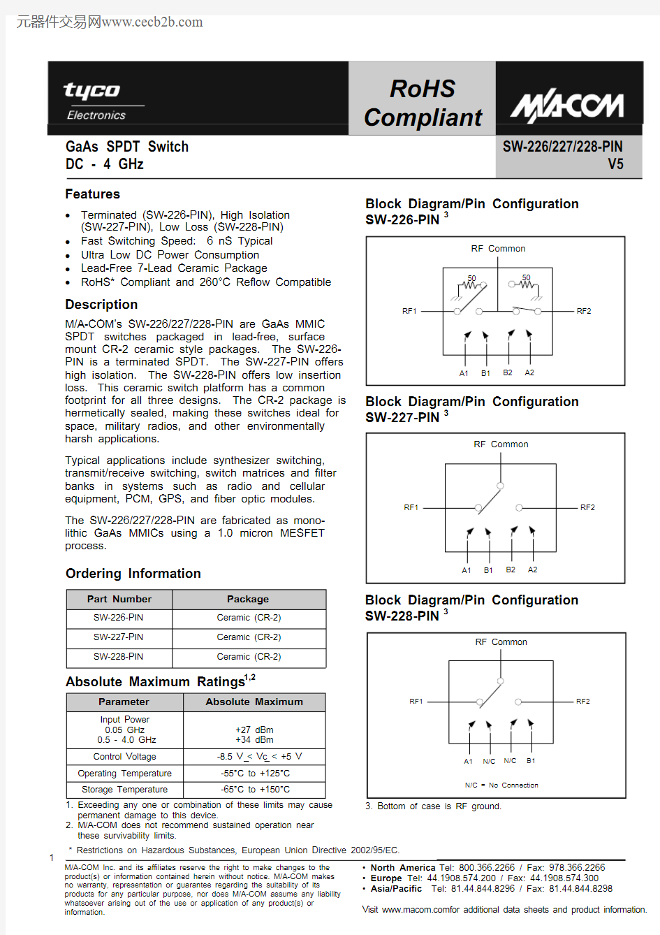
GaAs SPDT Switch DC - 4 GHz
SW-226/227/228-PIN
V5 Compliant
Electrical Specifications: T A = -55°C to +85°C, Vc = 0 V / -5 V, Z0 = 50 ?4
Parameter Test Conditions Units Min. Typ. Max.
Insertion Loss (SW-226-PIN) DC - 0.5 GHz
DC - 1 GHz
DC - 2 GHz
DC - 4 GHz dB
dB
dB
dB
—
—
—
—
—
—
—
—
0.9
1.0
1.2
1.5
Insertion Loss (SW-227-PIN) DC - 0.5 GHz
DC - 1 GHz
DC - 2 GHz
DC - 4 GHz dB
dB
dB
dB
—
—
—
—
—
—
—
—
0.9
1.0
1.1
1.4
Insertion Loss (SW-228-PIN) DC - 0.5 GHz
DC - 1 GHz
DC - 2 GHz
DC - 4 GHz dB
dB
dB
dB
—
—
—
—
—
—
—
—
0.7
0.7
0.8
1.0
Isolation (SW-226-PIN) DC - 0.5 GHz
DC - 1 GHz
DC - 2 GHz
DC - 4 GHz dB
dB
dB
dB
53
48
40
25
—
—
—
—
—
—
—
—
Isolation (SW-227-PIN) DC - 0.5 GHz
DC - 1 GHz
DC - 2 GHz
DC - 4 GHz dB
dB
dB
dB
55
50
40
35
—
—
—
—
—
—
—
—
Isolation (SW-228-PIN) DC - 0.5 GHz
DC - 1 GHz
DC - 2 GHz
DC - 4 GHz dB
dB
dB
dB
50
42
32
22
—
—
—
—
—
—
—
—
VSWR (SW-226-PIN) DC - 0.5 GHz
DC - 1 GHz
DC - 2 GHz
DC - 4 GHz Ratio
Ratio
Ratio
Ratio
—
—
—
—
—
—
—
—
1.2:1
1.4:1
1.6:1
2.3:1
VSWR (SW-227-PIN) DC - 0.5 GHz
DC - 1 GHz
DC - 2 GHz
DC - 4 GHz Ratio
Ratio
Ratio
Ratio
—
—
—
—
—
—
—
—
1.2:1
1.4:1
1.6:1
2.0:1
VSWR (SW-228-PIN) DC - 0.5 GHz
DC - 1 GHz
DC - 2 GHz
DC - 4 GHz Ratio
Ratio
Ratio
Ratio
—
—
—
—
—
—
—
—
1.2:1
1.2:1
1.3:1
1.9:1
Trise, Tfall 510% to 90% RF, 90% to 10% RF nS — 3 —
Ton, Toff 550% control to 90% RF, 50% control to 10% RF nS — 6 — Transients5 (SW-226-PIN,SW-227-PIN) In-Band mV — 30 — Transients5 (SW-228-PIN) In-Band mV — 10 —
4. See MIL-STD-883 for environmental screening options.
5. Faster switching speed can be achieved with enhanced driver waveform.
GaAs SPDT Switch DC - 4 GHz
SW-226/227/228-PIN
V5 Compliant
Parameter Test Conditions Units Min. Typ. Max.
Input P1dB 0.5 - 4 GHz, 0 / -5 VDC
0.05 GHz, 0 / -5 VDC
0.5 - 4 GHz, 0 / -8 VDC
0.05 GHz, 0 / -8 VDC dBm
dBm
dBm
dBm
—
—
—
—
27
21
33
26
—
—
—
—
IP2 For two-tone input power up to +13 dBm
0.5 - 4 GHz 0.05 GHz dBm
dBm
—
—
68
62
—
—
IP3 For two-tone input power up to +13 dBm
0.5 - 4 GHz 0.05 GHz dBm
dBm
—
—
46
40
—
—
Control Current │Vc│ = 0 to 0.2 V
│Vc│ = 5 V (SW-226-PIN, SW-227-PIN)
│Vc│ = 8 V (SW-226-PIN, SW-227-PIN)
│Vc│ = 5 V (SW-228-PIN)
│Vc│ = 8 V (SW-228-PIN) μA
μA
μA
μA
μA
—
—
—
—
—
—
110
—
50
—
20
—
600
—
300
Electrical Specifications (continued): T A = -55°C to +85°C, Vc = 0 V / -5 V, Z0 = 50 ?
Handling Procedures
Please observe the following precautions to avoid damage:
Static Sensitivity
Gallium Arsenide Integrated Circuits are sensitive to electrostatic discharge (ESD) and can be damaged by static electricity. Proper ESD control techniques should be used when handling these devices. SW-226-PIN and SW-227-PIN Truth Table 6,7
6. 0 = 0 V to -0.2 V, 1 = -5 V to -8 V
7. For the SW-227-PIN and SW-228-PIN only, when an RF
output is “OFF” it is shorted to case ground.
Control Input Condition of Switch,
RF Common to each
RF Port
A1 B1 A2 B2 RF1 RF2
1 0 0 1 ON OFF
0 1 1 0 OFF ON SW-228-PIN Truth Table 6,7
Condition of Switch,
RF Common to each
RF Port A1 B1 RF1 RF2
1 0 ON OFF
0 1 OFF ON
Control Input
GaAs SPDT Switch DC - 4 GHz
SW-226/227/228-PIN
V5
Compliant
Isolation
VSWR
Typical Performance Curves
Insertion Loss
1
2
3
4
Frequency (GHz)
1
2
3
4
Frequency (GHz)
1.0
1.2
1.4
1.6
1.8
2.0
1
2
3
4
Frequency (GHz)