DP2539_REV2.1

DP2539
High Precision CC/CV Primary-Side PWM Power Switch
GENERAL DESCRIPTION
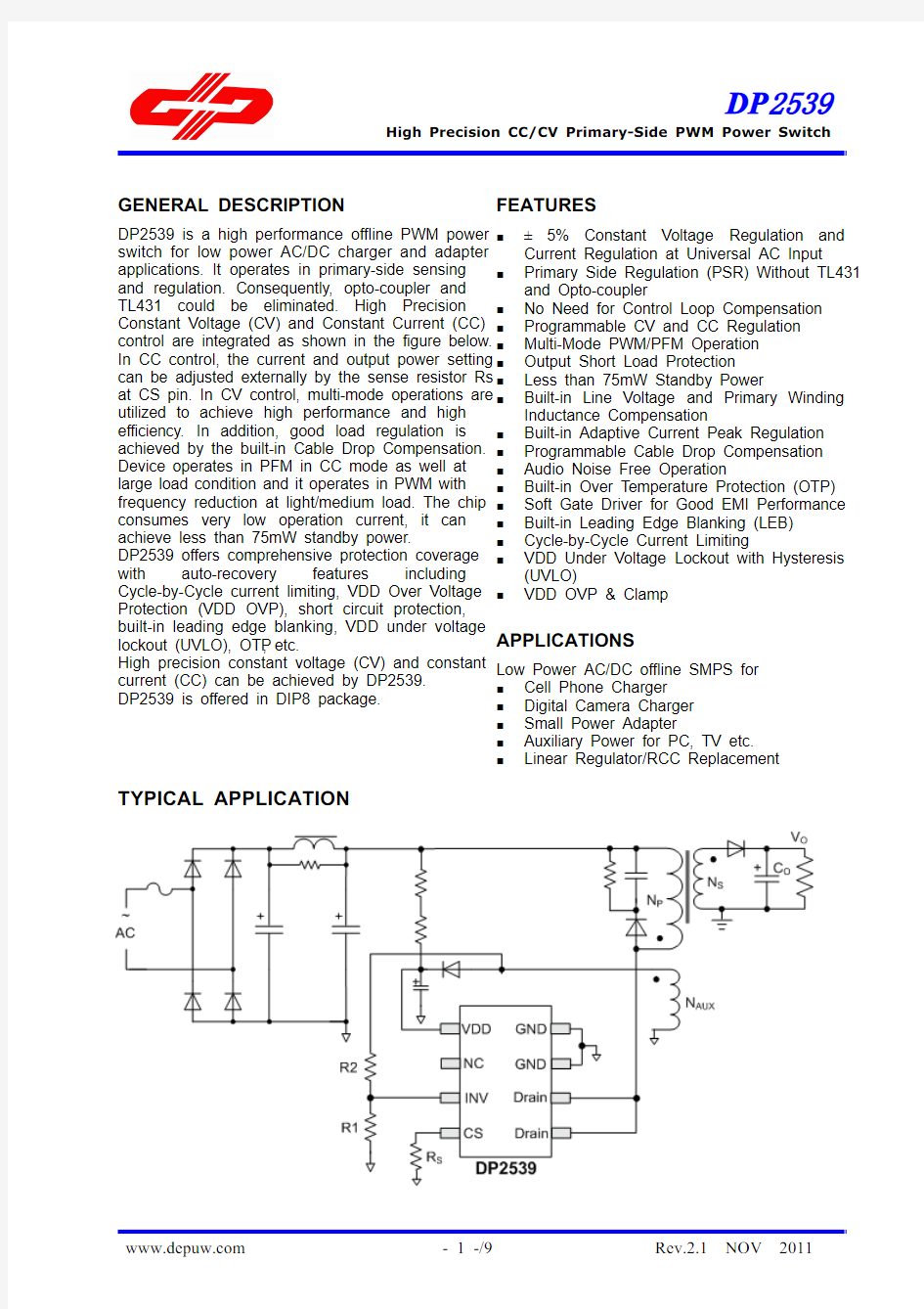
DP2539 is a high performance offline PWM power switch for low power AC/DC charger and adapter applications. It operates in primary-side sensing and regulation. Consequently, opto-coupler and TL431 could be eliminated. High Precision Constant Voltage (CV) and Constant Current (CC) control are integrated as shown in the figure below. In CC control, the current and output power setting can be adjusted externally by the sense resistor Rs at CS pin. In CV control, multi-mode operations are utilized to achieve high performance and high efficiency. In addition, good load regulation is achieved by the built-in Cable Drop Compensation. Device operates in PFM in CC mode as well at large load condition and it operates in PWM with frequency reduction at light/medium load. The chip consumes very low operation current, it can achieve less than 75mW standby power. DP2539 offers comprehensive protection coverage with auto-recovery features including Cycle-by-Cycle current limiting, VDD Over Voltage Protection (VDD OVP), short circuit protection, built-in leading edge blanking, VDD under voltage lockout (UVLO), OTP, etc. High precision constant voltage (CV) and constant current (CC) can be achieved by DP2539. DP2539 is offered in DIP8 package.
FEATURES
■ ■ ■ ■ ■ ■ ■ ■ ■ ■ ■ ■ ■ ■ ■ ■ ■ ■ ■ ■ ■ ■
5% Constant Voltage Regulation and Current Regulation at Universal AC Input Primary Side Regulation (PSR) Without TL431 and Opto-coupler No Need for Control Loop Compensation Programmable CV and CC Regulation Multi-Mode PWM/PFM Operation Output Short Load Protection Less than 75mW Standby Power Built-in Line Voltage and Primary Winding Inductance Compensation Built-in Adaptive Current Peak Regulation Programmable Cable Drop Compensation Audio Noise Free Operation Built-in Over Temperature Protection (OTP) Soft Gate Driver for Good EMI Performance Built-in Leading Edge Blanking (LEB) Cycle-by-Cycle Current Limiting VDD Under Voltage Lockout with Hysteresis (UVLO) VDD OVP & Clamp
±
APPLICATIONS
Low Power AC/DC offline SMPS for Cell Phone Charger Digital Camera Charger Small Power Adapter Auxiliary Power for PC, TV etc. Linear Regulator/RCC Replacement
TYPICAL APPLICATION
https://www.wendangku.net/doc/5912591647.html,
- 1 -/9
Rev.2.1 NOV 2011
DP2539
High Precision CC/CV Primary-Side PWM Power Switch
GENERAL INFORMATION
Pin Configuration The pin map of DIP8 package is shown as below.
Package Dissipation Rating Package DIP8
RθJA ( 75
℃/W)
Absolute Maximum Ratings Parameter Value Drain Voltage (off state) -0.3 to 600V VDD Zener Clamp Voltage VDD_Clamp VDD Clamp Continuous 10 mA Current CS Input Voltage -0.3 to 7V INV Input Voltage -0.3 to 7V Maximum Operating Junction o 150 C Temperature TJ Min/Max Storage Temperature o -55 to 150 C Tstg Lead Temperature (Soldering, o 260 C 10secs) Note: Stresses beyond those listed under “absolute maximum Ordering Information Part Number Description DP2539 DIP8, Rohs, 50Pcs/Tube
ratings” may cause permanent damage to the device. These are stress ratings only, functional operation of the device at these or any other conditions beyond those indicated under “recommended operating conditions” is not implied. Exposure to absolute maximum-rated conditions for extended periods may affect device reliability.
Output Power Table (1)
Part Number
230VAC 15%(2) (3) Adapter
±
85-265VAC Adapter(3)
DP2539 18W 15W Note 1. The Max. output power is limited by junction temperature Note 2. 230VAC or 100/115VAC with doublers Note 3. Typical continuous power in a non-ventilated enclosed adapter with sufficient drain pattern as a heat sink at 50
ambient.
℃
https://www.wendangku.net/doc/5912591647.html,
- 2 -/9
Rev.2.1 NOV 2011
DP2539
High Precision CC/CV Primary-Side PWM Power Switch
Marking Information
TERMINAL ASSIGNMENTS
Pin Num 1 2 3 4 5/6 7/8 Pin Name VDD NC INV CS Drain GND I/O P I I O P Description Power supply. No connect. The voltage feedback from auxiliary winding. Connected to resistor divider from auxiliary winding reflecting output voltage. Current sense input. The Power MOSFET Drain Ground.
https://www.wendangku.net/doc/5912591647.html,
- 3 -/9
Rev.2.1 NOV 2011
DP2539
High Precision CC/CV Primary-Side PWM Power Switch
BLOCK DIAGRAM
RECOMMENDED OPERATING CONDITION
Symbol VDD TA Parameter VDD Supply Voltage Operating Ambient Temperature Min 11 -40 Max 27 85 Unit V o C
https://www.wendangku.net/doc/5912591647.html,
- 4 -/9
Rev.2.1 NOV 2011
DP2539
High Precision CC/CV Primary-Side PWM Power Switch
ELECTRICAL CHARACTERISTICS
(TA = 25 C, VDD=18V if not otherwise noted) Symbol Parameter Supply Voltage Section (VDD Pin) Start-up current into VDD IVDD_st pin IVDD_Op Operation Current IVDD_standby Standby Current VDD Under Voltage VDD_ON Lockout Exit VDD Under Voltage VDD_OFF Lockout Enter VDD_OVP VDD OVP Threshold VDD Zener Clamp VDD_Clamp Voltage Feedback Input Section (INV Pin) Internal Error Amplifier VINV_REF (EA) Reference Input Short Load Protection VINV_SLP (SLP) Threshold Short Load Protection TINV_Short (SLP) Debounce Time Demagnetization VINV_DEM Comparator Threshold Toff_min Minimum OFF time Toff_max Maximum OFF time F_min Minimum frequency F_max Maximum frequency Maximum Cable Drop ICable_max compensation current Current Sense Input Section (CS Pin) CS Input Leading Edge TLEB Blanking Time Vcs(max) Current limiting threshold Over Current Detection TD_OCP and Control Delay Over temperature Protection TSD TRC Thermal Shutdown Thermal Recovery
O
Test Conditions
Min
Typ 2
Max 20 1.5 1 17.5 10 32 36.5
Unit uA mA mA V V V V
VINV=3V, VDD=20V 15 8 28 I(VDD ) = 7 mA 32.5
1 0.5 16.3 9 30 34.5
1.97
2.0 0.7 10 25 2 5 450
2.03
V V ms mV us ms Hz KHz uA
72 63
500 490 500 100 510
ns mV ns
°C °C
---
165 135
---
Power MOSFET Section (Drain Pin) Power MOSFET Drain VBR Source Breakdown Voltage Static Drain-Source On Rdson Resistance
600 4.5
V Ohm
https://www.wendangku.net/doc/5912591647.html,
- 5 -/9
Rev.2.1 NOV 2011
DP2539
High Precision CC/CV Primary-Side PWM Power Switch
CHARACTERIZATION PLOTS
?
https://www.wendangku.net/doc/5912591647.html,
- 6 -/9
Rev.2.1 NOV 2011
DP2539
High Precision CC/CV Primary-Side PWM Power Switch
OPERATION DESCRIPTION
DP2539 is a cost effective PWM power switch optimized for off-line low power AC/DC applications including battery chargers and adapters. It operates in Primary Side Regulation (PSR), thus opto-coupler and TL431 are not required. High precision CV and CC control can be achieved to meet most small power charger and adapter applications requirements. Startup Current and Start up Control Startup current of DP2539 is designed to be very low (typically 2uA) so that VDD could be charged up above UVLO threshold level and device starts up quickly. A large value startup resistor can therefore be used to minimize the power loss yet reliable startup in application. Operating Current The operating current of DP2539 is as low as 1mA. Good efficiency is achieved by the low operating current together with extended burst mode control schemes at No/light load conditions. Primary Side CC/CV Control DP2539 is designed to produce good CC/CV control. In charger applications, a discharged battery charging starts in CC portion of the curve until it is nearly full charged and smoothly switched to operate in CV portion of the curve. In an AC/DC adapter, the normal operation occurs only on the CV portion of the curve. The CC portion provides output current limiting. between the auxiliary winding and INV (pin 3), the auxiliary voltage is sampled at the end of the demagnetization and it is hold until the next sampling. The sampled voltage is compared with VINV_REF (2.0V) and the error is amplified by an internal Error Amplifier (EA). The internal EA output reflects the load condition and control the PWM switching frequency to regulate the output voltage, thus constant voltage (CV) can be achieved. When system enters over load condition, the output voltage falls down and the INV sampled voltage should be lower than 2V internal reference which makes system enter CC Mode automatically. Multi Mode CV Operation for High Efficiency DP2539 is a multi-mode PSR controller. In CV mode, the controller changes the mode of operation by sampling INV voltage. Under the medium to large load conditions, the IC operates in PWM mode, which improves the system audio noise performance. Under normal to light load conditions, the IC operates in PFM mode to achieve high efficiency. The IC can achieve less than 75mW standby power, as shown in Fig.2
Internal GATE Drive Signal Ipk_s Ipk Primary Inductor Current Secondary Inductor Current
Fig.2
Auxiliary Winding Voltage
Tdem Tsw
Fig.1 As shown by Fig 1, when the PWM switching is off the secondary side diode is conducted and the auxiliary winding voltage is proportion to the output voltage. Via a resistor divider connected
CC Operation Switching Frequency The switching frequency of DP2539 is adaptively controlled according to the load conditions and the operation modes. For flyback operation in DCM, the maximum output power is given by
Po MAX =
1 2 L P FSW I P 2
Where Lp indicate the inductance of primary winding and Ip is the peak current of primary winding.
https://www.wendangku.net/doc/5912591647.html,
- 7 -/9
Rev.2.1 NOV 2011
DP2539
High Precision CC/CV Primary-Side PWM Power Switch
Refer to the equation above, the change of the primary winding inductance results in the change of the maximum output power and the constant output current in CC mode. To compensate the change from variations of primary winding inductance, the switching frequency is locked by and internal loop such that the switching frequency is
response performance, which enables charger system to meet the USB charge requirements. Programmable Cable Drop Compensation In DP2539, cable drop compensation is implemented to achieve good load regulation. An offset voltage is generated at INV pin by an internal current flowing into the resistor divider. The current is proportional to the switching off time, as a result, it is inversely proportional to the output load current, thus the drop due to the cable loss can be compensated. As the load current decreases from full-load to no-load, the offset voltage at INV pin will increase. It can also be programmed by adjusting the resistance of the divider to compensate the drop for various cable lines used. The percentage of maximum compensation is
FSW =
1 2TDEM
Since TDEM is inversely proportional to the inductance, as a result, the product of Lp and Fsw is constant, thus the maximum output power and constant current in CC mode will not change as primary winding inductance changes. Up to 10% variation of the primary winding inductance can be compensated.
±
Adjustable CC Point and Output Power In DP2539, the CC point and maximum output power can be externally adjusted by external current sense resistor Rs at CS pin as illustrated in typical application diagram. The larger Rs, the smaller CC point is, and the smaller output power becomes, and vice versa as shown in Fig.3.
V is load compensation voltage and Vout is output voltage; For example: R1=3K , R2=18K , The percentage of maximum compensation is given by
Δ
?V Icable_max × (R1//R2 ) ≈ × 100% Vout VINV_REF
Ω
Ω
?V 63uA × (3K//18K ) = × 100% = 8.1% Vout 2V
Over Temperature Protection (OTP) O When the IC temperature is over 165 C, the IC shuts down. Only when the IC temperature drops O to 135 C, IC will restart. Output Short Load Protection In DP2539, the output is sampled on INV pin and then compared with a threshold of UVP (0.7V typically) after an internal blanking time (10ms typical). When sensed INV voltage is below 0.7V, the IC will enter into Short Load Protection (SLP) mode, in which the IC will enter into auto recovery protection mode. VDD OVP and Zener Clamp When VDD voltage is higher than 30V (typical), the IC will stop switching. This will cause VDD fall down to be lower than VDD_OFF (typical 9V) and then the system will restart up again. An internal 34.5V (typical) zener clamp is integrated to prevent the IC from damage. Soft Gate Drive DP2539 has a soft totem-pole gate driver with optimized EMI performance. An internal 16V clamp is added for MOSFET gate protection at higher than expected VDD input.
Fig.3 Current Sensing and Leading Edge Blanking Cycle-by-Cycle current limiting is offered in DP2539. The switch current is detected by a sense resistor into the CS pin. An internal leading edge blanking circuit is built in. During this blanking period (500ns, typical), the cycle-by-cycle current limiting comparator is disabled and cannot switch off the GATE driver. Audio Noise Free Operation DP2539 can provide audio noise free operation from full loading to zero loading. Optimized Dynamic Response In DP2539, an optimized dynamic response control is integrated to improve system dynamic
https://www.wendangku.net/doc/5912591647.html,
- 8 -/9
Rev.2.1 NOV 2011
DP2539
High Precision CC/CV Primary-Side PWM Power Switch
Package Dimension
A
Symbol A A1 A2 B B1 C D E E1 e L E2
Dimensions In Millimeters Min Max 3.710 5.334 0.381 3.175 3.600 0.350 0.650 1.524 (BSC) 0.200 0.360 9.000 10.160 6.200 6.600 7.320 7.920 2.540 (BSC) 2.921 3.810 8.200 9.525
E
A1
L
A2
Dimensions In Inches Min Max 0.146 0.210 0.015 0.125 0.142 0.014 0.026 0.06 (BSC) 0.008 0.014 0.354 0.400 0.244 0.260 0.288 0.312 0.1 (BSC) 0.115 0.150 0.323 0.375
https://www.wendangku.net/doc/5912591647.html,
- 9 -/9
Rev.2.1 NOV 2011