139CLL中文资料

Document Number: 28301For technical questions, contact: aluminumcaps1@https://www.wendangku.net/doc/5913005983.html,
https://www.wendangku.net/doc/5913005983.html,
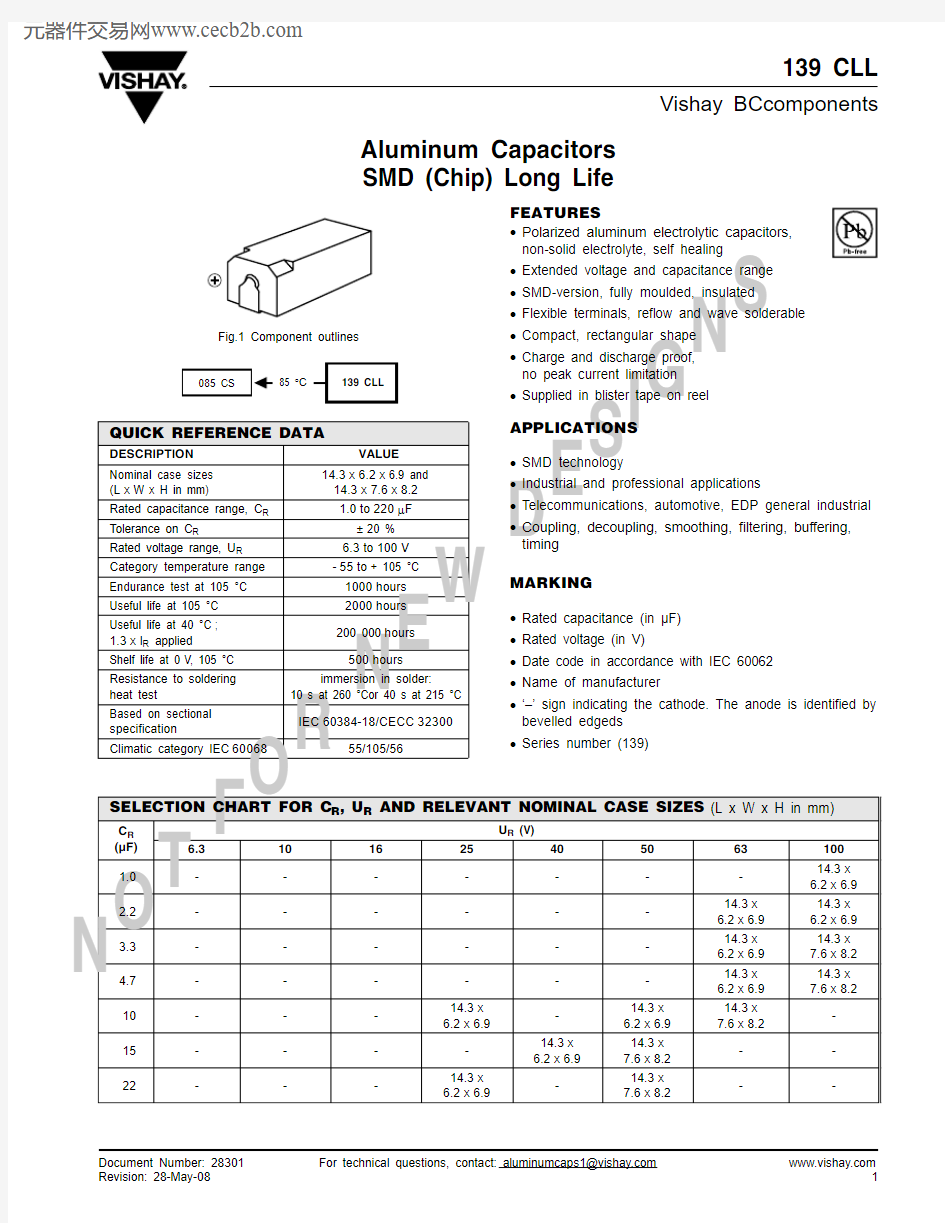
Aluminum Capacitors
SMD (Chip) Long Life
139 CLL
Vishay BCcomponents
N
O
T
F O
R
N
E
W
D
E
S
I G
N
S
FEATURES
?Polarized aluminum electrolytic capacitors,non-solid electrolyte, self healing ?Extended voltage and capacitance range
?SMD-version, fully moulded, insulated
?Flexible terminals, reflow and wave solderable
?Compact, rectangular shape
?Charge and discharge proof, no peak current limitation
?Supplied in blister tape on reel
APPLICATIONS
?SMD technology
?Industrial and professional applications
?Telecommunications, automotive, EDP general industrial ?Coupling, decoupling, smoothing, filtering, buffering,timing
MARKING
?Rated capacitance (in μF)?Rated voltage (in V)
?Date code in accordance with IEC 60062?Name of manufacturer
?‘–’ sign indicating the cathode. The anode is identified by bevelled edgeds ?Series number (139)
QUICK REFERENCE DATA
DESCRIPTION VALUE Nominal case sizes (L x W x H in mm)
14.3x 6.2x 6.9 and 14.3x 7.6x 8.2Rated capacitance range, C R 1.0to 220μF T olerance on C R
± 20 %Rated voltage range, U R 6.3to 100V Category temperature range - 55to + 105 °C Endurance test at 105 °C 1000hours Useful life at 105 °C 2000hours
Useful life at 40 °C ; 1.3x l R applied 200 000hours Shelf life at 0V, 105 °C 500hours
Resistance to soldering heat test
immersion in solder:
10 s at 260 °Cor 40 s at 215 °C
Based on sectional specification
IEC 60384-18/CECC 32300
Climatic category IEC 60068
55/105/56
Fig.1 Component outlines
SELECTION CHART FOR C R , U R AND RELEVANT NOMINAL CASE SIZES (L x W x H in mm)
C R (μF)U R (V)
6.31016254050631001.0-------14.3x 6.2x 6.92.2------14.3x 6.2x 6.914.3x 6.2x 6.93.3------14.3x 6.2x 6.914.3x
7.6x
8.24.7------14.3x 6.2x 6.914.3x 7.6x 8.2
10---14.3x 6.2x 6.9
-14.3x 6.2x 6.914.3x 7.6x 8.2
-15----14.3x 6.2x 6.9
14.3x 7.6x 8.2--22
-
-
-
14.3x 6.2x 6.9
-
14.3x 7.6x 8.2
--
139 CLL
Vishay
Aluminum Capacitors SMD (Chip) Long Life
https://www.wendangku.net/doc/5913005983.html, For technical questions, contact: aluminumcaps1@https://www.wendangku.net/doc/5913005983.html,
Document Number: 28301
N
O
T
F
S
I G
N
S
DIMENSIONS in millimeters
Table 1
Note
1.Detailed tape dimensions see section ‘PACKAGING’.
33---14.3x 6.2x 6.914.3x 7.6x 8.2
--
-
47--14.3x 6.2x 6.9
14.3x 7.6x 8.2
----68-14.3x 6.2x 6.9
-----
-10014.3x 6.2x 6.9
-14.3x 7.6x 8.2
-----150-14.3x 7.6x 8.2
------220
14.3x 7.6x 8.2
---
-
-
--
SELECTION CHART FOR C R , U R AND RELEVANT NOMINAL CASE SIZES (L x W x H in mm)
C R (μF)U R (V)
6.3101625405063100DIMENSIONS in millimeters, MASS AND PACKAGING QUANTITIES
NOMINAL CASE SIZE
L x W x H CASE CODE L max.
W max.
H max.
O max.
S
G max.
R min.
MASS (g)PACKAGING QUANTITIES PER REEL
14.3 x 6.2 x 6.9214.5 6.37.0513.0 2.157.5 4.7≈ 0.9570014.3 x 7.6 x 8.2
3
14.5
7.7
8.35
13.0
2.85
7.5
4.7
≈ 1.3
700
S ± 0.3
2
Fig.2 Dimensional o u tline
Document Number: 28301For technical questions, contact: aluminumcaps1@https://www.wendangku.net/doc/5913005983.html,
https://www.wendangku.net/doc/5913005983.html,
139 CLL
Aluminum Capacitors SMD (Chip) Long Life
Vishay
N
O
T
F
E
S
I G
N
S
MOUNTING
The capacitors are designed for automatic placement on to printed-circuit boards or hybrid circuits.
Optimum dimensions of soldering pads depend amongst others on soldering method, mounting accuracy, print lay-out and/or adjacent components.
For recommended soldering pad dimensions, refer to Fig.3and Table 2.
SOLDERING
Soldering conditions are defined by the curve, temperature versus time, where the temperature is that measured on the soldering pad during processing.
For maximum conditions of different soldering methods see Figs 4,5and 6.
Any temperature versus time curve which does not exceed the specified maximum curves may be applied.
AS A GENERAL PRINCIPLE, TEMPERATURE AND DURATION SHALL BE THE MINIMUM NECESSARY REQUIRED TO ENSURE GOOD SOLDERING
CONNECTIONS. HOWEVER, THE SPECIFIED MAXIMUM CURVES SHOULD NEVER BE EXCEEDED.
Table 3
RECOMMENDED SOLDERING PAD DIMENSIONS in millimeters (placement accuracy ± 0.25 mm)
NOMINAL CASE SIZE
L x W x H
FOR REFLOW SOLDERING
FOR WAVE SOLDERING
A B C D E F G A B C D E F G 14.3 x 6.2 x 6.915.88.8 3.5 2.88.016.27.718.610.0 4.3 5.08.820.511.514.3 x 7.6 x 8.2
15.8
8.8
3.5
2.8
8.0
16.2
9.1
18.6
10.0
4.3
6.0
8.8
21.5
13.0
solder land/solder paste pattern
solder resist pattern
occ u pied area
tracks or
d u mmy tracks
reflo w soldering
w a v e soldering
Fig.3 Recommended pad dimensions for reflo w and w a v e soldering
CURING CONDITIONS FOR SMD-GLUE
MAX. T amb
(°C)
MAX. EXPOSURE TIME
(minutes)
125301401015051602160
2
139 CLL
Vishay
Aluminum Capacitors SMD (Chip) Long Life
https://www.wendangku.net/doc/5913005983.html, For technical questions, contact: aluminumcaps1@https://www.wendangku.net/doc/5913005983.html,
Document Number: 28301
N
O
T
F O
R
N
E
W
D
E
S
I G
N
S
Note
Unless otherwise specified, all electrical values in Table 4 apply at T amb = 20 °C, P = 86 to 106 kPa, RH = 45 to 75 %.
ORDERING EXAMPLE
Electrolytic capacitor 139 series 100μF/16V; ± 20 %
Nominal case size: 14.3 x 7.6 x 8.2mm; taped on reel Ordering code: MAL213965101E3Former 12NC: 222213965101
280260
240220200180160140120100 80
0 50 100 150 200 250
T Pad
(°C)Fig.5 Maxim u m temperat u re load d u ring v apor phase reflo w soldering
f(s)
280260
240220200180160140120100 80
0 50 100 150 200 250
T Pad
(°C)Fig.7 Maxim u m temperat u re load d u ring (do ub le-) w a v e soldering
f(s)
ELECTRICAL DATA
SYMBOL DESCRIPTION
C R rated capacitance at 100 Hz , tolerance ± 20 %I R
rated RMS ripple current at 100Hz,105 °C I L5
max. leakage current after 5minutes at U R Tan δmax. dissipation factor at 100Hz Z max. impedance at 10 kHz
Document Number: 28301For technical questions, contact: aluminumcaps1@https://www.wendangku.net/doc/5913005983.html,
https://www.wendangku.net/doc/5913005983.html,
139 CLL
Aluminum Capacitors SMD (Chip) Long Life
Vishay
N
O
T
F O
R
N
E
W
D
E
S I G
N
S
Table 4
ELECTRICAL DATA AND ORDERING INFORMATION
U R (V)
C R 100Hz (μF)NOMINAL CASE SIZE L x W x H (mm)I R 100Hz 105 °C (mA)I L55min (μA)Tan δ100Hz Z 10kHz (Ω)ORDERING CODE MAL2139.......
6.310014.3x 6.2x 6.979 4.30.24 3.063101E322014.3x
7.6x
8.2120 5.80.24 1.463221E3
106814.3x 6.2x 6.971 4.40.20 2.964689E315014.3x 7.6x 8.2110 6.00.20 1.3
64151E316
4714.3x 6.2x 6.966 4.50.16 3.465479E310014.3x 7.6x 8.2100 6.20.16 1.665101E325
10
14.3x 6.2x 6.940 3.50.091266109E32214.3x 6.2x 6.948 4.10.14 5.566229E33314.3x 6.2x 6.959 4.70.14 3.766339E347
14.3x 7.6x 8.279 5.40.14 2.666479E340
1514.3x 6.2x 6.945 4.20.11
667159E33314.3x 7.6x 8.275 5.60.11 2.767339E350
10
14.3x 6.2x 6.940 4.00.09761109E31514.3x 7.6x 8.256 4.50.09 4.761159E32214.3x 7.6x 8.267 5.2
0.09 3.261229E363
2.2
14.3x 6.2x 6.919 3.30.092568228E33.314.3x 6.2x 6.923
3.40.092168338E3
4.714.3x 6.2x 6.928 3.60.091768478E31014.3x 7.6x 8.248
4.30.08868109E3100
1.0
14.3x 6.2x 6.912 3.20.095569108E32.214.3x 6.2x 6.919
3.40.092969228E33.31
4.3x 7.6x 8.227 3.70.081769338E34.7
14.3x 7.6x 8.2
33
3.9
0.08
1169478E3
ADDITIONAL ELECTRICAL DATA
PARAMETER
CONDITIONS
VALUE
Voltage Surge voltage for short periods
U s ≤1.15x U R Reverse voltage U rev ≤1V
Current
Leakage current after 1minute at U R I L1≤0.02 C R x U R +3after 5minute at U R
I L5≤0.002 C R x U R +3μA
Inductance
Equivalent series inductance (ESL)nominal case size 14.3x 6.2x 6.9mm typ. 18nH nominal case size 14.3x 7.6x 8.2mm typ. 28nH
Resistance
Equivalent series resistance (ESR)
calculated from tan δmax. and C R (see T able 4)
ESR = tan δ/2 πfC R
139 CLL
Vishay
Aluminum Capacitors SMD (Chip) Long Life
https://www.wendangku.net/doc/5913005983.html, For technical questions, contact: aluminumcaps1@https://www.wendangku.net/doc/5913005983.html,
Document Number: 28301
N
O
T
F O
R
N
E
D
E
CAPACITANCE
RIPPLE CURRENT AND USEFUL LIFE
104
103
102
10
f (Hz)
0.70.8
0.9
1.0
C 0C Fig.8 T ypical m u ltiplier of capacitance as a f u nction
of fre qu ency
C 0 = capacitance at 20 °C, 100 Hz
3.2.1.0.T am b (°C)
I A
I R CCC206
I A = act u al ripple c u rrent at 100 Hz
I R = act u al ripple c u rrent at 100 Hz, 105 °C (1) u sef u l life at 105 °C and I R applied: 2000 h
Fig.9 M u ltiplier of u sef u l life as a f u nction of am b ient temperat u re and ripple c u rrrent load
Document Number: 28301For technical questions, contact: aluminumcaps1@https://www.wendangku.net/doc/5913005983.html,
https://www.wendangku.net/doc/5913005983.html,
139 CLL
Aluminum Capacitors SMD (Chip) Long Life
Vishay
N
O
T
F O
R
N
E
W
D
E
S
I G
N
S
Table 5
MULTIPLIER OF RIPPLE CURRENT (I R ) AS A FUNCTION OF FREQUENCY
FREQUENCY
(Hz)
I R MULTIPLIER
U R =6.3to 16V
U R =25to 50V
U R =63to 100V
500.950.900.85
100 1.00 1.00 1.00
300 1.07 1.12 1.201000 1.12 1.20 1.303000 1.15 1.25 1.35≥ 10 000
1.20
1.30
1.40
TEST PROCEDURES AND REQUIREMENTS
TEST
PROCEDURE (quick reference)
REQUIREMENTS
NAME OF TEST REFERENCE Mounting
IEC 60384-18,subclause 4.3
shall be performed prior to tests mentioned below; reflow or (double-) wave soldering;
for maximum temperature load refer to chapter “Mounting”
ΔC/C:± 5 %tan δ≤spec. limit I L5≤spec. limit
Endurance IEC 60384-18/
CECC 32300,subclause 4.15
T amb =105 °C; U R applied;
1000 hours
U R ≤6.3 V ΔC/C:+15 /- 30 %U R ≥10V ΔC/C:± 15 %tan δ≤1.3 x spec. limit Z ≤2 x spec. limit I L5≤spec. limit
Useful life CECC 30301,
subclause 1.8.1
T amb =105 °C; U R and I R applied;
2000hours
U R ≤6.3 V ΔC/C:+ 45 /- 50 %U R ≥10 V ΔC/C:± 45 %tan δ≤3 x spec. limit Z ≤3 x spec. limit I L5≤spec. limit no short or open circuit total failure percentage: ≤ 1 %Shelf life (storage at high
temperature)
IEC 60384-18/CECC 32300,subclause 4.17
T amb =105 °C; no voltage applied;500hours
after test: U R to be applied for 30minutes, 24 to 48hours before measurement
for requirements
see ‘Endurance test’ above
Disclaimer Legal Disclaimer Notice
Vishay
All product specifications and data are subject to change without notice.
Vishay Intertechnology, Inc., its affiliates, agents, and employees, and all persons acting on its or their behalf (collectively, “Vishay”), disclaim any and all liability for any errors, inaccuracies or incompleteness contained herein or in any other disclosure relating to any product.
Vishay disclaims any and all liability arising out of the use or application of any product described herein or of any information provided herein to the maximum extent permitted by law. The product specifications do not expand or otherwise modify Vishay’s terms and conditions of purchase, including but not limited to the warranty expressed therein, which apply to these products.
No license, express or implied, by estoppel or otherwise, to any intellectual property rights is granted by this document or by any conduct of Vishay.
The products shown herein are not designed for use in medical, life-saving, or life-sustaining applications unless otherwise expressly indicated. Customers using or selling Vishay products not expressly indicated for use in such applications do so entirely at their own risk and agree to fully indemnify Vishay for any damages arising or resulting from such use or sale. Please contact authorized Vishay personnel to obtain written terms and conditions regarding products designed for such applications.
Product names and markings noted herein may be trademarks of their respective owners.
元器件交易网https://www.wendangku.net/doc/5913005983.html,
Document Number: https://www.wendangku.net/doc/5913005983.html,