ASTM A262 2015 奥氏体不锈钢晶间腐蚀敏感性检测标准方法

Designation:A262?15
Standard Practices for
Detecting Susceptibility to Intergranular Attack in Austenitic Stainless Steels1
This standard is issued under the?xed designation A262;the number immediately following the designation indicates the year of original adoption or,in the case of revision,the year of last revision.A number in parentheses indicates the year of last reapproval.A superscript epsilon(′)indicates an editorial change since the last revision or reapproval.
This standard has been approved for use by agencies of the U.S.Department of Defense.
1.Scope*
1.1These practices cover the following?ve tests:
1.1.1Practice A—Oxalic Acid Etch Test for Classi?cation of Etch Structures of Austenitic Stainless Steels(Sections4to 13,inclusive),
1.1.2Practice B—Ferric Sulfate-Sulfuric Acid Test for De-tecting Susceptibility to Intergranular Attack in Austenitic Stainless Steels(Sections14to25,inclusive),
1.1.3Practice C—Nitric Acid Test for Detecting Suscepti-bility to Intergranular Attack in Austenitic Stainless Steels (Sections26to36,inclusive),
1.1.4Practice E—Copper–Copper Sulfate–Sulfuric Acid Test for Detecting Susceptibility to Intergranular Attack in Austenitic Stainless Steels(Sections37to46,inclusive),and 1.1.5Practice F—Copper–Copper Sulfate–50%Sulfuric Acid Test for Detecting Susceptibility to Intergranular Attack in Molybdenum-Bearing Austenitic Stainless Steels(Sections 47to58,inclusive).
1.2The Oxalic Acid Etch Test is a rapid method of identifying,by simple etching,those specimens of certain stainless steel grades that are essentially free of susceptibility to intergranular attack associated with chromium carbide precipitates.These specimens will have low corrosion rates in certain corrosion tests and therefore can be eliminated (screened)from testing as“acceptable.”The etch test is applicable only to those grades listed in the individual hot acid tests and classi?es the specimens either as“acceptable”or as “suspect.”
1.3The ferric sulfate-sulfuric acid test,the copper–copper sulfate–50%sulfuric acid test,and the nitric acid test are based on weight loss determinations and,thus,provide a quantitative measure of the relative performance of specimens evaluated.In contrast,the copper–copper sulfate–16%sulfuric acid test is based on visual examination of bend specimens and,therefore, classi?es the specimens only as acceptable or nonacceptable.
1.4The presence or absence of intergranular attack in these tests is not necessarily a measure of the performance of the material in other corrosive environments.These tests do not provide a basis for predicting resistance to forms of corrosion other than intergranular,such as general corrosion,pitting,or stress-corrosion cracking.
N OTE1—See Appendix X1for information regarding test selection.
1.5The values stated in SI units are to be regarded as standard.The inch-pound equivalents are in parentheses and may be approximate.
1.6This standard does not purport to address all of the safety concerns,if any,associated with its use.It is the responsibility of the user of this standard to establish appro-priate safety and health practices and determine the applica-bility of regulatory limitations prior to use.Some speci?c hazards statements are given in10.1,20.1.1,20.1.9,31.3,34.4, 53.1.1,and53.1.10.
2.Referenced Documents
2.1ASTM Standards:2
A370Test Methods and De?nitions for Mechanical Testing of Steel Products
A380/A380M Practice for Cleaning,Descaling,and Passi-vation of Stainless Steel Parts,Equipment,and Systems D1193Speci?cation for Reagent Water
E3Guide for Preparation of Metallographic Specimens 2.2ASME Code:3
ASME Boiler&Pressure Vessel Code,Section IX
2.3ACS Speci?cations:4
Reagent Chemicals,Speci?cations and Procedures
1These practices are under the jurisdiction of ASTM Committee A01on Steel, Stainless Steel and Related Alloys and are the direct responsibility of Subcommittee A01.14on Methods of Corrosion Testing.
Current edition approved Sept.1,2015.Published September2015.Originally approved https://www.wendangku.net/doc/5016506544.html,st previous edition approved in2014as A262–14.DOI: 10.1520/A0262-15.
2For referenced ASTM standards,visit the ASTM website,https://www.wendangku.net/doc/5016506544.html,,or contact ASTM Customer Service at service@https://www.wendangku.net/doc/5016506544.html,.For Annual Book of ASTM Standards volume information,refer to the standard’s Document Summary page on the ASTM website.
3Available from American Society of Mechanical Engineers(ASME),ASME International Headquarters,Two Park Ave.,New York,NY10016-5990,http:// https://www.wendangku.net/doc/5016506544.html,.
4Available from American Chemical Society(ACS),1155Sixteenth Street,NW, Washington,DC20036,https://www.wendangku.net/doc/5016506544.html,
*A Summary of Changes section appears at the end of this standard Copyright?ASTM International,100Barr Harbor Drive,PO Box C700,West Conshohocken,PA19428-2959.United States
2.4ISO Standard:5
ISO 3651-2Determination of Resistance to Intergranular Corrosion of Stainless Steels—Part 2:Ferritic,Austenitic,and Ferritic-Austenitic (Duplex)Stainless Steels—Corrosion Test in Media Containing Sulfuric Acid 3.Purity of Reagents
3.1Purity of Reagents—Reagent grade chemicals shall be used in all tests.Unless otherwise indicated,it is intended that all reagents conform to the speci?cations of the Committee on Analytical Reagents of the American Chemical Society 6where such speci?cations are available.Other grades may be used,provided it is ?rst ascertained that the reagent is of sufficiently high purity to permit its use without lessening the accuracy of the test result.
3.2Purity of Water—Unless otherwise indicated,references to water shall be understood to mean reagent water as de?ned by Type IV of Speci?cation D1193.
PRACTICE A—OXALIC ACID ETCH TEST FOR CLASSIFICATION OF ETCH STRUCTURES OF
AUSTENITIC STAINLESS STEELS (1)74.Scope
4.1The Oxalic Acid Etch Test is used for acceptance of wrought or cast austenitic stainless steel material but not for rejection of https://www.wendangku.net/doc/5016506544.html,e of A262Practice A as a stand-alone test may reject material that the applicable hot acid test would ?nd acceptable;such use is outside the scope of this practice.4.2This test is intended to be used in connection with other evaluation tests described in these practices to provide a rapid method for identifying qualitatively those specimens that are certain to be free of susceptibility to rapid intergranular attack in these other tests.Such specimens have low corrosion rates in the various hot acid tests which require from 15to 240h of exposure.These specimens are identi?ed by means of their etch structures,which are classi?ed according to the criteria given in Section 11.
4.3The Oxalic Acid Etch Test may be used to screen specimens intended for testing in Practice B—Ferric Sulfate-Sulfuric Acid Test,Practice C—Nitric Acid Test,Practice E—Copper-Copper Sulfate–16%Sulfuric Acid Test,and Prac-tice F—Copper-Copper Sulfate–50%Sulfuric Acid Test.4.4Each of these other practices contains a table showing which classi?cations of etch structures on a given stainless steel grade are equivalent to acceptable or suspect performance in that particular test.Specimens having acceptable etch structures need not be subjected to the hot acid test.Specimens having suspect etch structures must be tested in the speci?ed hot acid solution.
4.5There are two classes of specimens to be considered:base metal,and process-affected metal.
4.5.1Process-affected metal contains any condition that affects the corrosion properties of the material in a non-uniform way,such as (but not limited to)welds;carburized.nitrided,or oxidized surfaces;mechanical deformation;and areas affected by heat.Base metal has none of these conditions.
4.5.2Because Practices B,C,and F involve immersing the entire specimen and averaging the mass loss over the total specimen area,and because welding,carburization,mechanical deformation,and the like affect only part of a specimen,the presence of process-affected metal in a specimen can affect the test result in an unpredictable way depending on the propor-tions of the area affected.
4.5.3If the presence of these or other localized conditions is a concern to the purchaser,then tests that do not average the mass loss over the total specimen surface area,such as Practice A,the Oxalic Acid Etch Test,or Practice E,the Copper–Copper Sulfate–Sulfuric Acid Test for Detecting Susceptibility to Intergranular Attack in Austenitic Stainless Steels,should be considered.
5.Summary of Practice
5.1A specimen representative of the material to be evalu-ated is polished to a speci?ed ?nish and over-etched using oxalic acid electrolytically.The etched specimen is then examined using a metallurgical microscope.The etched struc-ture is compared with reference photographs to determine whether the material is acceptable or suspect.Suspect material is then subjected to the speci?ed hot acid immersion test.
6.Signi?cance and Use
6.1Use of the etch test allows rapid acceptance of speci?c lots of material without the need to perform time-consuming and costly hot acid immersion tests on those lots.
7.Apparatus
7.1Etching Cell:
7.1.1An etching cell may be assembled using components as described in this section.Alternatively,a commercial electropolisher/etcher (as used for metallographic sample preparation)may be used for small specimens provided the current density requirement of 10.2is met.
7.1.2Source of Direct Current—Battery,generator,or rec-ti?er capable of supplying about 15V and 20A.
7.1.3Ammeter—For direct current;used to measure the current on the specimen to be etched.
7.1.4Variable Resistance—Used to control the current on the specimen to be etched.
7.1.5Cathode—A stainless steel container,for example,a 1-L (1-qt)stainless steel beaker.
7.1.5.1Alternate Cathode—A piece of ?at stainless steel at least as large as the specimen surface.
7.1.6Electrical Clamp—To hold the specimen to be etched and to complete the electrical circuit between the specimen and the power source such that the specimen is the anode of the cell.
5
Available from International Organization for Standardization (ISO),1,ch.de la V oie-Creuse,CP 56,CH-1211Geneva 20,Switzerland,https://www.wendangku.net/doc/5016506544.html,.6
For suggestions on the testing of reagents not listed by the American Chemical Society,see Analar Standards for Laboratory Chemicals ,BDH Ltd.,Poole,Dorset,U.K.,and the United States Pharmacopeia and National Formulary ,U.S.Pharma-copeial Convention,Inc.(USPC),Rockville,MD.7
The boldface numbers in parentheses refer to a list of references at the end of this
standard.
--`,`,``,``,`,,`,,,,,,```,`,,```-`-`,,`,,`,`,,`---
7.1.7The power source,resistor,and ammeter must be sized appropriately for providing and controlling the current as speci?ed in10.2of this practice.
7.1.8As described,the electrolyte container is the cathode; it may be a stainless steel beaker or fabricated from stainless steel such as by welding a section of tube or pipe to a?at plate or sheet.Alternatively,the electrolyte container may be glass (or other non-conducting,corrosion resisting material)in lieu of a stainless steel container,and the cathode may be a?at plate or sheet of a corrosion resisting alloy.In this latter case,the?at surface of the cathode must be at least as large as,facing,and approximately centered on,the prepared surface of the speci-men.Other con?gurations of the electrodes might not provide uniform etching over the specimen surface.In any case,the size and shape of the specimen dictate the size and construction of the etching cell and of the power source and controls.The overriding principle is that the etch needs to be uniform over the surface to be examined.
7.2Metallurgical Microscope—For examination of etched microstructures at250to500diameters.
8.Reagents and Materials
8.1Etching Solution(10%)—Dissolve100g of reagent grade oxalic acid crystals(H2C2O4·2H2O)in900mL of reagent water.Stir until all crystals are dissolved.
8.1.1Alternate Etching Solution(See10.7)—Dissolve100g of reagent grade ammonium persulfate((NH4)2S2O8)in 900mL of reagent water.Stir until dissolved.
9.Sampling and Test Specimens
9.1The speci?ed hot acid test provides instructions for sampling and for specimen preparation such as a sensitization heat treatment.Additional instructions speci?c to Practice A follow:
9.2The preferred specimen is a cross-section including the product surface to be exposed in service.Only such?nishing of the product surface should be performed as is required to remove foreign material.
9.3Whenever practical,use a cross-sectional area of1cm2 or more.If any cross-sectional dimension is less than1cm, then the other dimension of the cross-section should be a minimum of1cm.When both dimensions of the product are less than1cm,use a full cross section.
9.4Polishing—On all types of materials,polish cross sec-tional surfaces through CAMI/ANSI600[FEPA/ISO P1200]in accordance with Guide E3prior to etching and examination. Not all scratches need to be removed.
10.Procedure
10.1(Warning—Etching should be carried out under a ventilated hood.Gas,which is rapidly evolved at the electrodes with some entrainment of oxalic acid,is poisonous and irritating to mucous membranes.)
10.2Etch the polished specimen at1A/cm2for1.5min.
10.2.1To obtain the correct speci?ed current density: 10.2.1.1Measure the total immersed area of the specimen to be etched in square centimetres.
10.2.1.2Adjust the variable resistance until the ammeter reading in amperes is equal to the total immersed area of the specimen in square centimetres.
10.3A yellow-green?lm is gradually formed on the cath-ode.This increases the resistance of the etching cell.When this occurs,remove the?lm by rinsing the inside of the stainless steel beaker(or the steel used as the cathode)with an acid such as30%HNO3.
10.4The temperature of the etching solution gradually increases during etching.Keep the temperature below50°C. This may be done by alternating two containers.One may be cooled in tap water while the other is used for etching.
10.4.1The rate of heating depends on the total current (ammeter reading)passing through the cell.Therefore,keep the area to be etched as small as possible while at the same time meeting the requirements of desirable minimum area to be etched.
10.5Avoid immersing the clamp holding the specimen in the etching solution.
10.6Rinsing—Following etching,rinse the specimen thor-oughly in hot water and then in acetone or alcohol to avoid crystallization of oxalic acid on the etched surface during drying.
10.7It may be difficult to reveal the presence of step structures on some specimens containing molybdenum(AISI 316,316L,317,317L),which are free of chromium carbide sensitization,by electrolytic etching with oxalic acid.In such cases,an alternate electrolyte of ammonium persulfate may be used in place of oxalic acid.(See8.1.1.)An etch for5or10 min at1A/cm2in a solution at room temperature readily develops step structures on such specimens.
11.Classi?cation of Etch Structures
11.1Examine the etched surface on a metallurgical micro-scope at250×to500×for wrought steels and at about250×for cast steels.
11.2Examine the etched cross-sectional areas thoroughly by complete traverse from inside to outside diameters of rods and tubes,from face to face on plates.
11.2.1Microscopical examination of a specimen shall be made on metal unaffected by cold-working,carburization, welding,and the like.If any of these conditions are found,note their presence in the report.
11.3Classify the etch structures into the following types (Note2):
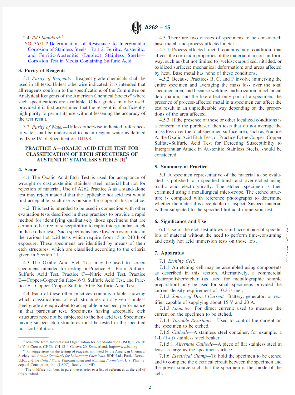
11.3.1Step Structure(Fig.1)—Steps only between grains, no ditches at grain boundaries.
11.3.2Dual Structure(Fig.2)—Some ditches at grain boundaries in addition to steps,but no single grain completely surrounded by ditches.
11.3.3Ditch Structure(Fig.3)—One or more grains com-pletely surrounded by ditches.
11.3.4Isolated Ferrite(Fig.4)—Observed in castings and welds.Steps between austenite matrix and ferrite pools. 11.3.5Interdendritic Ditches(Fig.5)—Observed in castings and welds.Deep interconnected
ditches.--` , ` , ` ` , ` ` , ` , , ` , , , , , , ` ` ` , ` , , ` ` ` -` -` , , ` , , ` , ` , , ` ---
11.3.6End-Grain Pitting I (Fig.6)—Structure contains a few deep end-grain pits along with some shallow etch pits at 500×.(Of importance only when the nitric acid test is used.)11.3.7End-Grain Pitting II (Fig.7)—Structure contains numerous,deep end-grain pits at 500×.(Of importance only when nitric acid test is used.)
N OTE 2—All photomicrographs were made with specimens that were etched under standard conditions:10%oxalic acid,room temperature,1.5min at 1A/cm 2.
11.4The evaluation of etch structures containing only steps and of those showing grains completely surrounded by ditches in every ?eld can be carried out relatively rapidly.In cases that appear to be dual structures,more extensive examination is required to determine if there are any grains completely encircled.If an encircled grain is found,classify the steel as a ditch structure.
11.4.1On stainless steel castings (also on weld metal),the steps between grains formed by electrolytic oxalic acid etching tend to be less prominent than those on wrought materials
or
FIG.1Step Structure (500×)(Steps Between Grains,No Ditches
at Grain
Boundaries)
FIG.2Dual Structure (250×)(Some Ditches at Grain Boundaries in Addition to Steps,but No One Grain Completely
Surrounded)
FIG.3Ditch Structure (500×)(One or More Grains Completely
Surrounded by
Ditches)
FIG.4Isolated Ferrite Pools (250×)(Observed in Castings and Welds.Steps Between Austenite Matrix and Ferrite
Pools)
--`,`,``,``,`,,`,,,,,,```,`,,```-`-`,,`,,`,`,,`---
are entirely absent.However,any susceptibility to intergranular attack is readily detected by pronounced ditches.
11.4.2Some wrought specimens,especially from bar stock,may contain a random pattern of pits.If these pits are sharp and so deep that they appear black (Fig.7)it is possible that the specimen may be susceptible to end grain attack in nitric acid only.Therefore,even though the grain boundaries all have step
structures,specimens having as much or more end grain pitting than that shown in Fig.7cannot be safely assumed to have low nitric acid rates and should be subjected to the nitric acid test whenever it is speci?ed.Such sharp,deep pits should not be confused with the shallow pits shown in Figs.1and https://www.wendangku.net/doc/5016506544.html,e of Etch Structure Classi?cations
12.1The use of these classi?cations depends on the hot acid corrosion test for which stainless steel specimens are being screened by etching in oxalic acid and is described in each of the practices.
13.Precision and Bias
13.1Precision and Bias—No information is presented about either the precision or bias of Practice A—Oxalic Acid Etch Test for classi?cation of Etch Structures of Austenitic Stainless Steels since the test result is nonquantitative.
PRACTICE B—FERRIC SULFATE–SULFURIC ACID TEST FOR DETECTING SUSCEPTIBILITY
TO INTERGRANULAR ATTACK IN AUSTENITIC STAINLESS STEELS (2)14.Scope
14.1This practice describes the procedure for conducting the boiling 120-h ferric sulfate–50%sulfuric acid test which measures the susceptibility of austenitic stainless steels to intergranular attack.
14.2The presence or absence of intergranular attack in this test is not necessarily a measure of the performance of the material in other corrosive environments.The test does not provide a basis for predicting resistance to forms of
corrosion
FIG.5Interdendritic Ditches (250×)(Observed in Castings and
Welds.Deep Interconnected
Ditches)
N OTE 1—To differentiate between the types of pits,use a magni?cation of 500×and focus in the plane of etched surface.The pits which now appear completely black are end grain pits.
FIG.6End Grain Pitting I (500×)(A Few Deep End Grain Pits
(See 1in Figure)and Shallow Etch Pits
(2))
N OTE 1—This or a greater concentration of end grain pits at 500×(using standard etching conditions)indicates that the specimen must be tested when screening is for nitric acid test.
FIG.7End Grain Pitting II
(500×)
--`,`,``,``,`,,`,,,,,,```,`,,```-`-`,,`,,`,`,,`---
other than intergranular,such as general corrosion,pitting,or stress-corrosion cracking.
15.Summary of the Ferric Sulfate-Sulfuric Acid Practice
B
15.1A specimen representative of the material to be evalu-ated is immersed in a boiling solution of ferric sulfate and sulfuric acid for a speci?ed time.The resulting mass loss is converted to a corrosion rate,which is compared to a speci?ed maximum value to determine whether the material has the resistance to attack expected of the grade of material being tested.
16.Signi?cance and Use
16.1The ferric sulfate-sulfuric acid test detects susceptibil-ity to intergranular attack associated primarily with chromium carbide precipitate in unstabilized austenitic stainless steels, and to intergranular attack associated with sigma phase. 16.2The corrosion potential of the ferric sulfate-sulfuric acid test has been reported as0.6V versus a standard calomel electrode(SCE),as compared with0.75to1.0V for Practice C, and0.1V for Practices E and F.(3)
N OTE3—A higher corrosion potential indicates more severely oxidizing conditions.
17.Rapid Screening Test
17.1Before testing in the ferric sulfate-sulfuric acid test, specimens of certain grades of stainless steels(see Table1) may be given a rapid screening test in accordance with procedures given in Practice A,Oxalic Acid Etch Test for Classi?cation of Etch Structures of Austenitic Stainless Steels. Preparation,etching,and the classi?cation of etch structures are described therein.The use of etch structure evaluations in connection with the ferric sulfate-sulfuric acid test is speci?ed in Table1.
17.2Heat treat the material in accordance with22.1prior to performing the etch test.
17.3Ignore“process-affected”areas(see Section21);ap-plication of the ferric sulfate-sulfuric acid test to process-affected areas is currently outside the scope of Practice B. 17.4Corrosion test specimens having acceptable etch struc-tures in the Oxalic Acid Etch Test will be essentially free of intergranular attack in the ferric sulfate-sulfuric acid test.Such specimens are acceptable without testing in the ferric sulfate-sulfuric acid test.All specimens having suspect etch structures shall be tested in the ferric sulfate-sulfuric acid test.
18.Apparatus
18.1The apparatus is illustrated in Fig.8.
N OTE4—Other ground glass joints,such as the45/40joint may also be used.
18.1.1An Allihn condenser with a minimum of four bulbs and with a ground glass joint to match that of the?ask. 18.1.1.1Substitutions for this condenser or?ask are not allowed.Speci?cally,the cold-?nger type of condenser with standard Erlenmeyer?asks shall not be used.Corrosion rates obtained using the cold-?nger type of condenser are lower than those obtained using the Allihn type of condenser whether due to loss of vapor or to higher oxygen content in the solution or both.Such lower corrosion rates lead to acceptance of material that should be rejected.
18.1.2A1-L Erlenmeyer?ask with a ground glass joint to match that of the condenser.The?ask opening limits the size of the specimen;a larger opening is desirable.
TABLE1Use of Etch Structure Classi?cations from the Oxalic Acid Etch Test with Ferric Sulfate-Sulfuric Acid Test A
Grade Acceptable Etch
Structures
Suspect Etch Structures B
304Step,dual,end grain,I&II Ditch
304L Step,dual,end grain,I&II Ditch
316Step,dual,end grain,I&II Ditch
316L Step,dual,end grain,I&II Ditch
317Step,dual,end grain,I&II Ditch
317L Step,dual,end grain,I&II Ditch
CF-3Step,dual,isolated ferrite pools Ditch,interdendritic ditches CF-8Step,dual,isolated ferrite pools Ditch,interdendritic ditches CF-3M Step,dual,isolated ferrite pools Ditch,interdendritic ditches CF-8M Step,dual,isolated ferrite pools Ditch,interdendritic ditches A Grades not listed in this table either have not been evaluated for use of Practice A with Practice B or have been found to give acceptable results in the etch test while giving unacceptable results in Practice B.In the latter case Practices A would pass material that should have been subjected to the ferric sulfate-sulfuric acid test.
B Specimens having
these structures shall be tested in the ferric sulfate-sulfuric
acid test.
FIG.8Apparatus for Ferric Sulfate-Sulfuric Acid Test
--`,`,``,``,`,,`,,,,,,```,`,,```-`-`,,`,,`,`,,`---
18.1.3Glass cradle(Note5)—Can be supplied by a glass-blowing shop.It must be sized so as to?t,with the specimen, through the?ask opening.It must be designed to allow free ?ow of the testing solution around the specimen.
N OTE5—Other equivalent means of specimen support,such as glass hooks or stirrups,may also be used.
18.1.4Boiling Chips—Used to prevent bumping.
18.1.5High Vacuum Silicone Grease—For the ground glass joint.
18.1.6Hot plate,capable of providing heat for continuous boiling of the solution.
18.1.7An analytical balance capable of weighing to the nearest0.001g.
N OTE6—During testing,there is some deposition of iron oxides on the upper part of the Erlenmeyer?ask.This can be readily removed,after test completion,by boiling a solution of10%hydrochloric acid in the?ask.
18.1.8Desiccator—For storage of prepared specimens prior to testing.
19.Reagents and Materials
19.1Ferric Sulfate Hydrate(Fe2(SO4)3·xH2O),about75% (Fe2(SO4)3)by mass.
19.1.1Ferric sulfate is a speci?c additive that establishes and controls the corrosion potential.Substitutions are not permitted.
19.2Sulfuric Acid(H2(SO)4),95.0to98.0%by mass.
20.Ferric Sulfate-Sulfuric Acid Test Solution
20.1Prepare600mL of50%(49.4to50.9%)solution as follows:
20.1.1(Warning—Protect the eyes and use rubber gloves for handling acid.Place the test?ask under a hood.)
20.1.2First,measure400.0mL of Type IV reagent water and pour into the Erlenmeyer?ask.
20.1.3Then measure236.0mL of reagent-grade sulfuric acid.Add the acid slowly and with constant stirring to the water in the Erlenmeyer?ask to avoid boiling by the heat evolved.
N OTE7—Loss of vapor results in concentration of the acid.
20.1.4Weigh25g of reagent-grade ferric sulfate to the nearest0.1g and add to the sulfuric acid solution.
20.1.5Drop boiling chips into the?ask.
20.1.6Lubricate ground glass joint with silicone grease.
20.1.7Cover?ask with condenser and circulate cooling water.
20.1.8Boil the solution until all ferric sulfate is dissolved (see Note7).
20.1.9(Warning—It has been reported that violent boiling resulting in acid spills can occur.It is important to ensure that the concentration of acid does not increase and that an adequate number of boiling chips(which are resistant to attack by the test solution)are present.)
21.Sampling
21.1Obtain and prepare only base metal samples.
21.1.1There are two classes of specimens to be considered: base metal,and process-affected metal.Process-affected metal contains any condition that affects the corrosion properties of the material in a non-uniform way,such as(but not limited to) welds;carburized.nitrided,or oxidized surfaces;mechanical deformation;and areas affected by heat.Base metal has none of these conditions.
21.1.2The Practice B test involves immersing the entire specimen and averaging the mass loss over the entire surface of the specimen.Welding,carburization,mechanical deformation, and the like,affect only part of a specimen.
21.1.3The mass loss rate from process-affected metal is expected to differ from that from base metal;the presence of process-affected metal in a specimen will affect the calculated test result in an unpredictable way.
21.1.4If the presence of these or other localized conditions is a concern to the purchaser,then tests that do not average the mass loss over the total specimen surface area,such as Practice A,the Oxalic Acid Etch Test,or Practice E,the Copper–Copper Sulfate–16%Sulfuric Acid Test for Detecting Susceptibility to Intergranular Attack in Austenitic Stainless Steels,should be considered.Details of the test and acceptance criteria shall be as agreed by the purchaser and producer.
21.2Unless otherwise speci?ed by the purchaser,the pro-cedures for obtaining representative base metal samples,for removing the specimens from the samples,and the number of specimens shall be at the discretion of the producer.
22.Preparation of Test Specimens
22.1Heat treat extra-low carbon and stabilized grades at 650to675°C(1200to1250°F),which is the range of maximum carbide precipitation,prior to testing.The length of time of heating,and the method of subsequent cooling used for this sensitizing treatment together with the corresponding maximum permissible corrosion rate shall be as agreed be-tween the material producer and purchaser.
N OTE8—The most commonly used sensitizing treatment is1h at 675°C(1250°F).
22.2Prepare the specimens,each having a total surface area of5to20cm2.
22.3Where feasible for the product form,grind all the specimen surfaces using CAMI/ANSI120[FEPA/ISO P120] paper-backed,wet or dry,closed coated abrasive paper,with water as a coolant.If abrasive paper is used dry,polish slowly to avoid overheating.Do not use abrasives with grinding aids; some grinding aids contain?uorides that can affect the measured corrosion rate.
22.4Remove all traces of oxide scale and heat tint formed during heat treatments.Any scale that cannot be removed by grinding(for example,in stamped numbers)may be removed by using one of the pickling solutions described in Practice A380/A380M,Table A1.1.(Residual oxide scale causes gal-vanic action and consequent activation in the test solution.)
22.5Measure the specimens,including the inner surfaces of any holes,to the nearest0.05mm(0.001in.)and calculate the total exposed area.
22.6Degrease the specimens using suitable nonchlorinated agents,such as soap and lukewarm water,or acetone.Dry
the --` , ` , ` ` , ` ` , ` , , ` , , , , , , ` ` ` , ` , , ` ` ` -` -` , , ` , , ` , ` , , ` ---
specimens and weigh each one to the nearest0.001g.Store the specimens in a desiccator until the test is to be performed. 23.Procedure
23.1If the test solution is not already boiling,bring it to boiling.
23.1.1Keep the?ask covered with the condenser(with cooling water?owing)except when inserting or removing specimens.(See Note7.)
23.2Turn off the heat source and allow the boiling to subside.
23.3Place specimens in glass cradles.
23.4Uncover the?ask.
23.5Insert the specimens.
23.6Replace the condenser immediately,restore cooling water?ow,and turn on the heat source.
23.7Mark the liquid level on the?ask to provide a check on vapor loss,which would result in concentration of the acid.If there is an appreciable change in the level,repeat the test with fresh solution and reground and reweighed specimens.
23.8Continue the immersion of the specimens for a total of 120h(?ve days),then remove the specimens,rinse in water or acetone,and dry.
23.9Weigh the specimens and subtract the new weights from original weights.
23.10Intermediate weighings are usually not necessary.The test can be run without interruption for120h.However,if preliminary results are desired,the specimens can be removed at any time for weighing.
23.11Changes to the solution during the120-h test periods are not necessary.
23.12If the corrosion rate is extraordinarily high,as evi-denced by a change in the color(from yellow to green)of the solution,additional ferric sulfate inhibitor may need to be added during the test.If the total weight loss of all the specimens in a?ask exceeds2g,more ferric sulfate must be added.(During the test,ferric sulfate is consumed at a rate of 10g for each1g of dissolved stainless steel.)
23.13Several specimens may be tested simultaneously.The number(3or4)is limited only by the number of glass cradles that can be?tted into the?ask.
24.Calculation and Report
24.1The effect of the acid solution on the material is measured by determining the loss of weight of the specimen. The corrosion rates should be reported as millimetres of penetration per month(Note9),calculated as follows:
Millimetre per month5~73053W!/~A3t3d!(1) where:
t=time of exposure,h,
A=area,cm2,
W=weight loss,g,and
d=density,g/cm3
for chromium-nickel steels,d=7.9g/cm3
for chromium-nickel-molybdenum steels,d=8.00g/cm3 N OTE9—Conversion factors to other commonly used units for corro-sion rates are as follows:
Millimetres per month×0.04=inches per month
Millimetres per month×0.47=inches per year
Millimetres per month×12=millimetres per year
Millimetres per month×472=mils per year
Millimetres per month×1000×density/3=milligrams per square decimetre per day
Millimetres per month×1.39×density=grams per square metre per hour 25.Precision and Bias
25.1Precision—The precision of Practice B is being deter-mined.
25.2Bias—This practice has no bias because the resistance to intergranular corrosion is de?ned only in terms of this practice.
PRACTICE C—NITRIC ACID TEST FOR
DETECTING SUSCEPTIBILITY TO
INTERGRANULAR ATTACK IN
AUSTENITIC STAINLESS STEELS
26.Scope
26.1This practice describes the procedure for conducting the boiling nitric acid test(2)as employed to measure the relative susceptibility of austenitic stainless steels to inter-granular attack.
26.2The presence or absence of intergranular attack in this test is not necessarily a measure of the performance of the material in other corrosive environments;in particular,it does not provide a basis for predicting resistance to forms of corrosion other than intergranular,such as general corrosion, pitting,or stress-corrosion cracking.
27.Summary of Test Method C,the Nitric Acid Test 27.1A specimen representative of the material to be evalu-ated is immersed in a boiling solution of nitric acid for a speci?ed time.The resulting mass loss is converted to a corrosion rate,which is compared to a speci?ed maximum value to determine whether the material has the resistance to attack expected of the grade of material being tested.
28.Signi?cance and Use
28.1The nitric acid test detects susceptibility to rapid intergranular attack associated with chromium carbide precipi-tate
28.2The corrosion potential of the nitric acid test(Practice
C)has been reported as0.75to1.0V versus a standard calomel electrode as compared with0.6V for Practice B,and0.1V for Practices E and F.(3)
N OTE10—Higher corrosion potential indicates more severely oxidizing conditions.The high corrosion potential of the nitric acid test suggests that it should be invoked only when the material is destined for nitric acid service.
29.Rapid Screening Test
29.1Before testing in the nitric acid test,specimens of certain grades of stainless steel,as given in Table2,may
be --`,`,``,``,`,,`,,,,,,```,`,,```-`-`,,`,,`,`,,`---
given a rapid screening test in accordance with procedures given in Practice A,Oxalic Acid Etch Test for Classi?cation of Etch Structures of Austenitic Stainless Steels.The use of the etch structure evaluations in connection with the nitric acid test is speci?ed in Table 2.
29.2Heat treat the material in accordance with 33.1prior to performing the etch test.
29.3Ignore “process-affected”areas,if any (see Section 32);application of the nitric acid test to process-affected areas is currently outside the scope of Practice C.
29.4Corrosion test specimens having acceptable etch struc-tures in the Oxalic Acid Etch Test will be essentially free of intergranular attack in the nitric acid test;such specimens are acceptable without testing in the nitric acid test.All specimens having suspect etch structures shall be tested in the nitric acid test.
30.Apparatus
30.1Container—A 1-L Erlenmeyer ?ask equipped with a cold ?nger-type condenser,as illustrated in Fig.9.
30.2Specimen Supports—Glass hooks,stirrups,or cradles for supporting the specimens in the ?ask fully immersed at all times during the test and so designed that specimens tested in the same container do not come in contact with each other.
30.3Heater—A means for heating the test solutions and of keeping them boiling throughout the test period.An electrically heated hot plate is satisfactory for this purpose.
30.4Balance—An analytical balance capable of weighing to at least the nearest 0.001g.
30.5Desiccator—For storage of prepared specimens prior to testing.
31.Nitric Acid Test Solution
31.1The test solution shall be 65.060.2weight %as nitric acid determined by analysis.
31.2Prepare this solution by adding reagent grade nitric acid (HNO 3Table 3)to reagent water at the rate of 108mL of reagent water per litre of reagent nitric acid.
31.3(Warning—Protect the eyes and use rubber gloves for handling acid.Place the test ?ask under a hood.)
31.4The nitric acid used shall conform to the American Chemical Society Speci?cations for Reagent Chemicals and the additional requirements of this test method as shown in Table 3.32.Sampling
32.1Obtain and prepare only base metal samples.
32.1.1There are two classes of specimens to be considered:base metal,and process-affected metal.Process-affected metal contains any condition that affects the corrosion properties of the material in a non-uniform way,such as (but not limited to)welds;carburized.nitrided,or oxidized surfaces;mechanical deformation;and areas affected by heat.Base metal has none of these conditions.
32.1.2The Practice C test involves immersing the entire specimen and averaging the mass loss over the entire surface of the specimen.Welding,carburization,mechanical deformation,and the like,affect only part of a specimen.
32.1.3The mass loss rate from process-affected metal is expected to differ from that from base metal;the presence of process-affected metal in a specimen will affect the calculated test result in an unpredictable way.
32.1.4If the presence of these or other localized conditions is a concern to the purchaser,then tests that do not average the mass loss over the total specimen surface area,such as Practice A,the Oxalic Acid Etch Test,or Practice E,the Copper–Copper Sulfate–Sulfuric Acid Test for Detecting Susceptibility to
TABLE 2Use of Etch Structure Classi?cation from Oxalic Acid
Etch Test with Nitric Acid Test A
Grade Acceptable Etch Structures
Suspect Etch Structures B
AISI 304Step,dual,end grain I Ditch,end grain II AISI 304L Step,dual,end grain I
Ditch,end grain II
ACI CF-8Step,dual,isolated ferrite pools Ditch,interdendritic ditches ACI CF-3
Step,dual,isolated ferrite
pools
Ditch,interdendritic ditches
A
Grades not listed in this table either have not been evaluated for use of Practice A with Practice B or have been found to give acceptable results in the etch test while giving unacceptable results in Practice B.In the latter case Practice A would pass material that should have been subjected to the ferric sulfate-sulfuric acid test.B
Specimens having these structures
shall be tested in the nitric acid test.
FIG.9Flask and Condenser for Nitric Acid Test
TABLE 3Nitric Acid Composition Limits
Minimum
Maximum Nitric Acid (HNO 3),mass percent 69.071.0Ash,ppm
{5Chloride as Cl,ppm {0.5Sulfate,as (SO 4),ppm {1Arsenic (As),ppm {0.01Heavy metals,as Pb,ppm
{0.2Iron,(Fe),ppm
{
0.2
Additional limits per Practices A262Fluorine (F),ppm
{1Phosphate (PO 4),ppm
{0.2
--`,`,``,``,`,,`,,,,,,```,`,,```-`-`,,`,,`,`,,`---
Intergranular Attack in Austenitic Stainless Steels,should be considered.Details of the test and acceptance criteria shall be as agreed by the purchaser and producer.
32.2Unless otherwise speci?ed by the purchaser,the pro-cedures for obtaining representative base metal samples,for removing the specimens from the samples,and the number of specimens shall be at the discretion of the producer.
32.3When specimens are cut by shearing,the sheared edges shall be re?nished by machining or grinding prior to testing.
33.Preparation of Test Specimens
33.1Heat treat extra-low carbon and stabilized grades at 650to675°C(1200to1250°F),which is the range of maximum carbide precipitation,prior to testing.The length of time of heating,and the method of subsequent cooling used for this sensitizing treatment together with the corresponding maximum permissible corrosion rate shall be as agreed be-tween the material producer and purchaser.
N OTE11—The most commonly used sensitizing treatment is1h at 675°C(1250°F).
N OTE12—The size and shape of the specimen must be considered with respect to available facilities for accurate weighing and the volume of test solution to be used.Normally,the maximum convenient weight of a specimen is about100g.In the case of bar,wire,and tubular products,the proportion of the total area represented by the exposed cross section may in?uence the results.Cross-sectional areas in these products may be subject to end grain attack in nitric acid.The proportion of end grain in the specimen should therefore be kept low unless such surface is actually to be exposed in service involving nitric acid.In this latter case,the proportion of end grain in the specimen should be kept high.
33.2Where feasible for the product form,grind all the specimen surfaces using CAMI/ANSI120[FEPA/ISO P120] paper-backed,wet or dry,closed coated abrasive paper,with water as a coolant.If abrasive paper is used dry,polish slowly to avoid overheating.Do not use abrasives with grinding aids; some grinding aids contain?uorides that can affect the measured corrosion rate.
33.3Remove all traces of oxide scale and heat tint formed during heat treatments.Any scale that cannot be removed by grinding(for example,in stamped numbers)may be removed by using one of the pickling solutions described in Practice A380/A380M,Table A1.1.
33.4Measure the specimen,including the inner surfaces of any holes to the nearest0.05mm(0.001in.),and calculate the total exposed area in cm2.
33.5Degrease the specimen using suitable nonchlorinated agents,such as soap and lukewarm water,or acetone(Note13). Dry the specimens and weigh each one to the nearest0.001g. Store the specimens in a desiccator until the test is to be performed.
N OTE13—The cleaning treatment described may be supplemented by immersing the specimen in nitric acid(for example,20weight%at49to 60°C(120to140°F))for20min,followed by rinsing,drying,and weighing.In the case of small-diameter tubular specimens which cannot be conveniently resurfaced on the inside,it is desirable to include in the preparation an immersion in boiling nitric acid(65%)for2to4h using the same apparatus as for the actual test.The purpose of these treatments is to remove any surface contamination that may not be accomplished by the regular cleaning method and which may increase the apparent weight loss of the specimen during the early part of the test.
33.6The standard test is to test only one specimen of each material or lot of material.However,in case of dispute,the use of at least two specimens for check purposes is recommended.
34.Procedure
34.1Use a sufficient quantity of the nitric acid test solution to cover the specimens and to provide a volume of at least20 mL/cm2(125mL/in.2)of specimen surface.Normally,a volume of about600mL is used.
34.2Use a separate container for each test specimen. 34.2.1As many as three specimens may be tested in the same container provided that they all are of the same grade and all show satisfactory resistance to corrosion.
34.2.2If more than one of the specimens tested in the same container fail to pass the test,retest all the specimens in separate containers.
N OTE14—Excessive corrosion of one specimen may result in acceler-ated corrosion of the other specimens tested with it.Excessive corrosion may often be detected by changes in the color of the test solution,and it may be appropriate to provide separate containers for such specimens without waiting until the end of the test period.A record should be made showing which specimens were tested together.
34.3After the specimens have been placed in the acid in the container,pass cooling water through the condenser,bring the acid to a boil on the hot plate,and keep boiling throughout the test period(Note15).After each test period,rinse the speci-mens with water and treat by scrubbing with rubber or a nylon brush under running water to remove any adhering corrosion products,then dry and weigh them.Drying may be facilitated, if desired,by dipping the specimens in acetone after they are scrubbed.
34.4(Warning—It has been reported that violent boiling resulting in acid spills can occur.It is important to ensure that the concentration of acid does not increase and that an adequate number of boiling chips(which are resistant to attack by the test solution)are present.)
N OTE15—Take care to prevent contamination of the testing solution, especially by?uorides,either before or during the test.Experience has shown that the presence of even small amounts of hydro?uoric acid will increase the corrosion rate in the nitric acid test.It is not permissible,for example,to conduct nitric-hydro?uoric acid tests in the same hood with nitric acid tests.
34.5The standard test consists of?ve boiling periods of 48h each with a fresh test solution being used in each period.
34.5.1A combination of one48-h period and two96-h periods(not necessarily in that order)instead of?ve48-h test periods may be used if so agreed by the purchaser.
35.Calculation and Report
35.1Calculation—The effect of the acid on the material shall be measured by determining the loss of weight of the specimen after each test period and for the total of the test https://www.wendangku.net/doc/5016506544.html,ing Eq1,calculate the corrosion rate for each specimen for each test period,and for the total of the test periods.
35.2Report—Report the calculated corrosion rates for the individual periods in chronological order,as well as
the --` , ` , ` ` , ` ` , ` , , ` , , , , , , ` ` ` , ` , , ` ` ` -` -` , , ` , , ` , ` , , ` ---
average for the ?ve test periods.If the modi?ed test periods (34.5.1)are used,then identify each result as to the sequence and length of the test period.36.Precision and Bias
36.1Precision—The precision of Practice C is being deter-mined.
36.2Bias—This practice has no bias because the resistance to intergranular corrosion is de?ned only in terms of this practice.
PRACTICE E—COPPER-COPPER SULFATE–16%
SULFURIC ACID TEST FOR DETECTING SUSCEPTIBILITY TO INTERGRANULAR
ATTACK IN AUSTENITIC STAINLESS STEELS (4,5)37.Scope
37.1This practice describes the procedure by which the copper–copper sulfate–16%sulfuric acid test is conducted to determine the susceptibility of austenitic stainless steels to intergranular attack.The presence or absence of intergranular corrosion in this test is not necessarily a measure of the performance of the material in other corrosive media.The test does not provide a basis for predicting resistance to other forms of corrosion,such as general corrosion,pitting,or stress-corrosion cracking.38.Rapid Screening Test
38.1Before testing in the copper–copper sulfate–16%sul-furic acid test,specimens of certain grades of stainless steel (see Table 4)may be given a rapid screening test in accordance with the procedures given in Practice A (Sections 4through 13).Preparation,etching,and the classi?cation of etch struc-tures are described therein.The use of etch-structure evalua-tions in connection with the copper–copper sulfate–16%sulfuric acid test is speci?ed in Table 4.
38.1.1Corrosion test specimens having acceptable etch structures in the Oxalic Acid Etch Test will be essentially free of intergranular attack in the copper–copper sulfate–16%sulfuric acid test.Such specimens are acceptable without
testing in the copper–copper sulfate–16%sulfuric acid test.All specimens having suspect etch structures must be tested in the copper–copper sulfate–16%sulfuric acid test.
38.1.2Heat treat the material when required by and in accordance with 43.3.1prior to performing the etch test.39.Summary of Practice
39.1A suitable sample of an austenitic stainless steel,embedded in copper shot or grindings,is exposed to boiling acidi?ed copper sulfate solution for 15h.After exposure in the boiling solution,the specimen is bent.Intergranular cracking or crazing is evidence of susceptibility.
39.2Alternative Testing Procedures:
39.2.1Unless prohibited by the purchaser in the purchase order,the supplier is permitted to meet the requirements of Practice E by performing a test in accordance with ISO 3651–2,Method A,provided that the testing period shall be a minimum of 15h.When a sensitization treatment is required,sensitization heat treatment T1[700°C 610°C (1292°F 618°F),30min,water quench]shall be used unless the supplier and purchaser shall agree upon preparation of welded test pieces to be tested in the as-welded condition.39.2.2When this alternative test procedure is used,it shall be noted on the test report.40.Apparatus
40.1The basic apparatus is described in Section 18.40.2Specimen Supports—An open glass cradle capable of supporting the specimens and copper shot or grindings in the ?ask is recommended.
N OTE 16—It may be necessary to embed large specimens,such as from heavy bar stock,in copper shot on the bottom of the test ?ask.A copper cradle may also be used.
40.3Heat Source—Any gas or electrically heated hot plate may be utilized for heating the test solution and keeping it boiling throughout the test period.
41.Acidi?ed Copper Sulfate Test Solution
41.1Dissolve 100g of reagent grade copper sulfate (CuSO 4·5H 2O)in 700mL of distilled water,add 100mL of sulfuric acid (H 2SO 4,cp,sp gr 1.84),and dilute to 1000mL with distilled water.
N OTE 17—The solution will contain approximately 6weight %of anhydrous CuSO 4and 16weight %of H 2SO 4.
42.Copper Addition
42.1Electrolytic grade copper shot or grindings may be used.Shot is preferred for its ease of handling before and after the test.
42.2A sufficient quantity of copper shot or grindings is to be used to cover all surfaces of the specimen whether it is in a vented glass cradle or embedded in a layer of copper shot on the bottom of the test ?ask.
42.3The amount of copper used,assuming an excess of metallic copper is present,is not critical.The effective galvanic coupling between copper and the test specimen may have importance (6).
TABLE 4Use of Etch Structure Classi?cations from the Oxalic Acid Etch Test with the Copper–Copper Sulfate–16%Sulfuric
Acid Test
Grade Acceptable Etch Structures Suspect Etch Structures A
AISI 201Step,dual,end grain I and II Ditch AISI 202Step,dual,end grain I and II Ditch AISI 301Step,dual,end grain I and II Ditch AISI 304Step,dual,end grain I and II Ditch AISI 304L Step,dual,end grain I and II Ditch AISI 304H Step,dual,end grain I and II Ditch AISI 316Step,dual,end grain I and II Ditch AISI 316L Step,dual,end grain I and II Ditch AISI 316H Step,dual,end grain I and II Ditch AISI 317Step,dual,end grain I and II Ditch AISI 317L Step,dual,end grain I and II Ditch AISI 321Step,dual,end grain I and II Ditch AISI
347
Step,
dual,
end
grain
I and
II
Ditch
A
Specimens having these structures must be tested in the copper–copper sulfate–16%sulfuric acid
test.
--`,`,``,``,`,,`,,,,,,```,`,,```-`-`,,`,,`,`,,`---
42.4The copper shot or grindings may be reused if they are cleaned in warm tap water after each test.43.Specimen Preparation
43.1The size of the sample submitted for test and the area from which it is to be taken (end or middle of coil,midway surface and center,and so forth)is generally speci?ed in the agreement between the purchaser and the seller.The testing apparatus dictates the ?nal size and shape of the test specimen.The specimen con?guration should permit easy entrance and removal through the neck of the test container.
43.1.1Table 5may be used as a guide to determine acceptable specimen sizes.There may be restrictions placed on specimen size by the testing apparatus.
43.1.2Specimens obtained by shearing should have the sheared edges machined or ground off prior to testing.Care should be taken when grinding to avoid overheating or “burning.”A “squared”edge is desirable.
43.2Any scale on the specimens should be removed me-chanically unless a particular surface ?nish is to be evaluated.Chemical removal of scale is permissible when this is the case.Mechanical removal of scale should be accomplished with 120-grit iron-free aluminum oxide abrasive.
43.2.1Each specimen should be degreased using a cleaning solvent such as acetone,alcohol,ether,or a vapor degreaser prior to being tested.
43.3All austenitic material in the “as-received”(mill-annealed)condition should be capable of meeting this test.43.3.1Specimens of extra-low-carbon and stabilized grades are tested after sensitizing heat treatments at 650to 675°C (1200to 1250°F),which is the range of maximum carbide precipitation.The most commonly used sensitizing treatment is
1h at 675°C.Care should be taken to avoid carburizing or nitriding the specimens.The heat treating is best carried out in air or neutral salt.
N OTE 18—The sensitizing treatment 675°C is performed to check the effectiveness of stabilized and 0.03%maximum carbon materials in resisting carbide precipitation,hence,intergranular attack.
44.Test Conditions
44.1The volume of acidi?ed copper sulfate test solution used should be sufficient to completely immerse the specimens and provide a minimum of 8mL/cm 2(50mL/in.2)of specimen surface area.
44.1.1As many as three specimens can be tested in the same container.It is ideal to have all the specimens in one ?ask to be of the same grade,but it is not absolutely necessary.The solution volume-to-sample area ratio is to be maintained.44.1.2The test specimen(s)should be immersed in ambient test solution,which is then brought to a boil and maintained boiling throughout the test period.Begin timing the test period when the solution reaches the boiling point.
N OTE 19—Measures should be taken to minimize bumping of the solution when glass cradles are used to support specimens.A small amount of copper shot (eight to ten pieces)on the bottom of the ?ask will conveniently serve this purpose.
44.1.3The time of the test shall be a minimum of 15h,unless a longer time is agreed upon between the purchaser and the producer.If not 15h,the test time shall be speci?ed on the test report.Fresh test solution would not be needed if the test were to run 48or even 72h.(If any adherent copper remains on the specimen,it may be removed by a brief immersion in concentrated nitric acid at room temperature.)
N OTE 20—Results in the literature indicate that this test is more sensitive if it is run for longer times (3,7).
45.Bend Test
45.1The test specimen shall be bent through 180°and over a diameter equal to the thickness of the specimen being bent (see Fig.10).In no case shall the specimen be bent over a
TABLE 5Sizes of Test Specimens
Type of Material
Size of Test Specimen
Wrought wire or rod:
Up to 6mm (?in.)in diameter,incl Full diameter by 75mm (3in.)(min)long
Over 6mm (?in.)in diameter
Cylindrical segment 6mm (?in.)thick by 25mm (1in.)(max)wide by 75to 125mm (3to 5in.)long A
Wrought sheet,strip,plates,or ?at rolled products:
Up to 5mm (3?16in.)thick,incl
Full thickness by 9to 25mm ("to 1in.)wide by 75mm (3in.)(min)long
Over 5mm (3?16in.)thick
5to 13mm (3?16to ?in.)thick by 9to 25mm ("to 1in.)wide by 75mm (3in.)(min)long B
Tubing:
Up to 38mm (1?in.)in diameter,incl Full ring,25mm (1in.)wide C Over 38mm (1?in.)in diameter A circumferential segment 75mm
(3in.)(min)long cut from a 25mm (1-in.)wide ring D
A
When bending such specimens,the curved surface shall be on the outside of the bend.B
One surface shall be an original surface of the material under test and it shall be on the outside of the bend.Cold-rolled strip or sheets may be tested in the thickness supplied.C
Ring sections are not ?attened or subjected to any mechanical work before they are subjected to the test solution.D
Specimens from welded tubes over 38mm (1?in.)in diameter shall be taken with the weld on the axis of the
bend.
FIG.10A Bent Copper–Copper Sulfate–Sulfuric Acid
Test
Specimen
--`,`,``,``,`,,`,,,,,,```,`,,```-`-`,,`,,`,`,,`---
smaller radius or through a greater angle than that speci?ed in the product speci?cation.In cases of material having low ductility,such as severely cold worked material,a180°bend may prove https://www.wendangku.net/doc/5016506544.html,ers shall inform those conducting the Practice E test when the material is in the low ductility highly stressed condition,such as highly cold worked material. Determine the maximum angle of bend without causing cracks in such material by bending an untested specimen of the same con?guration as the specimen to be tested.After exposure to the acidi?ed copper–copper sulfate sulfuric acid test solution, the maximum angle of bend without causing cracks as deter-mined from untested low ductility specimens shall be utilized in evaluation of the specimens exposed to the acidi?ed copper–copper sulfate sulfuric acid test solution.The angle of bend utilized in evaluating tested specimens shall be reported.
45.1.1Duplicate specimens shall be obtained from sheet material so that both sides of the rolled samples may be bent. This will assure detection of intergranular attack resulting from carburization of one surface of sheet material during the?nal stages of rolling.
N OTE21—Identify the duplicate specimen in such a manner as to ensure both surfaces of the sheet material being tested are subjected to the tension side of the bends.
45.1.2Samples machined from round sections or cast ma-terial shall have the curved or original surface on the outside of the bend.
45.1.3The specimens are generally bent by holding in a vise and starting the bend with a hammer.It is generally completed by bringing the two ends together in the vise.Heavy specimens may require bending in a?xture of suitable design.An air or hydraulic press may also be used for bending the specimens.
45.1.4Tubular products should be?attened in accordance with the?attening test,prescribed in Test Methods and De?nitions A370.
45.1.5When agreed upon between the purchaser and the producer,the following shall apply to austenitic stainless steel plates4.76mm(0.1875in.)and thicker:
45.1.5.1Samples shall be prepared according to Table5.
45.1.5.2The radius of bend shall be two times the sample thickness,and the bend axis shall be perpendicular to the direction of rolling.
45.1.5.3Welds on material4.76mm(0.1875in.)and thicker shall have the above bend radius,and the weld-base metal interface shall be located approximately in the centerline of the bend.
45.1.5.4Face,root,or side bend tests may be performed, and the type of bend test shall be agreed upon between the purchaser and the producer.The bend radius shall not be less than that required for mechanical testing in the appropriate material speci?cation(for base metal)or in ASME Code Section IX(for welds).
46.Evaluation
46.1The bent specimen shall be examined under low(5to 20×)magni?cation(see Fig.11).The appearance of?ssures
or FIG.11Passing Test Specimen—View of the Bent Area(20×Magni?cation Before
Reproduction)
cracks indicates the presence of intergranular attack(see Fig.
12).
46.1.1When an evaluation is questionable(see Fig.13),the presence or absence of intergranular attack shall be determined by the metallographic examination of the outer radius of a longitudinal section of the bend specimen at a magni?cation of 100to250×.
46.1.2Cracking that originates at the edge of the specimen shall be disregarded.The appearance of deformation lines, wrinkles,or“orange peel”on the surface,without accompa-nying cracks or?ssures,shall be disregarded also.
46.1.3Cracks suspected as arising through poor ductility shall be investigated by bending a similar specimen that was not exposed to the boiling test solution.A visual comparison between these specimens should assist in interpretation. PRACTICE F—COPPER-COPPER SULFATE–50% SULFURIC ACID TEST FOR DETERMINING SUSCEPTIBILITY TO INTERGRANULAR ATTACK IN AUSTENITIC STAINLESS STEELS
47.Scope
47.1This practice describes the procedure for conducting the boiling copper–copper sulfate–50%sulfuric acid test, which measures the susceptibility of stainless steels to inter-granular attack.
47.2The presence or absence of intergranular attack in this test is not necessarily a measure of the performance of the material in other corrosive environments.The test does not provide a basis for predicting resistance to forms of corrosion other than intergranular,such as general corrosion,pitting,or stress-corrosion cracking.48.Summary of Test Method F,the Copper–Copper
Sulfate–50%Sulfuric Acid Test
48.1A specimen representative of the material to be evalu-ated is immersed in a boiling solution of copper sulfate and sulfuric acid for a speci?ed time.A piece of copper is also immersed in the solution to maintain a constant corrosion potential.The resulting mass loss is converted to a corrosion rate,which is compared to a speci?ed maximum value to determine whether the material has the resistance to attack expected of the grade of material being tested.
49.Signi?cance and Use
49.1The copper–copper sulfate–sulfuric acid test detects susceptibility to intergranular attack associated primarily with chromium carbide precipitate in unstabilized cast austenitic stainless steels and in certain wrought grades.
49.2The copper–copper sulfate–sulfuric acid test does not detect susceptibility to intergranular attack associated primarily with sigma phase.
49.3The corrosion potential of the copper–copper sulfate-–sulfuric acid test has been reported as0.1V as compared with 0.6V for Practice B,0.75to1.0V for Practice C,and0.1V for Practice E.(3)
N OTE22—Higher corrosion potential indicates more severely oxidizing conditions.
50.Rapid Screening Test
50.1Before testing in the copper–copper sulfate–50%sul-furic acid test,specimens of certain grades of stainless steels (see Table6)may be given a rapid screening test in accordance with procedures given in Practice A,Oxalic Acid Etch Test
for FIG.12Failing Test Specimen(Note the many intergranular?ssures.Bent Area at20×Magni?cation Before
Reproduction.)
--`,`,``,``,`,,`,,,,,,```,`,,```-`-`,,`,,`,`,,`---
Classi?cation of Etch Structures of Austenitic Stainless Steels.Preparation,etching,and the classi?cation of etch structures are described therein.The use of etch structure evaluations in connection with the copper–copper sulfate–50%sulfuric acid test is speci?ed in Table 6.
50.2Heat treat the material in accordance with 55.1prior to performing the etch test.
50.3Ignore “process-affected”areas (see 54.1.1);applica-tion of the etch test to these areas is currently outside the scope of Practice F.
50.4Corrosion test specimens having acceptable etch struc-tures in the Oxalic Acid Etch Test will be essentially free of intergranular attack in the copper–copper sulfate–50%sulfuric acid test.Such specimens are acceptable without testing in the copper–copper sulfate–50%sulfuric acid test.All specimens having suspect etch structures shall be tested in the copper-–copper sulfate–50%sulfuric acid test.
51.Apparatus
51.1The basic apparatus is described in Section 18.
51.1.1Substitutions for this condenser or ?ask are not allowed.Speci?cally,the cold-?nger type of condenser with standard Erlenmeyer ?asks shall not be used.Corrosion rates obtained using the cold-?nger type of condenser are lower than those obtained using the Allihn type of condenser whether due to loss of vapor or to higher oxygen content in the solution or both.
52.Reagents and Materials
52.1Cupric Sulfate Pentahydrate (CuSO 4·5H 2O);about 64%(CuSO 4)by mass.
52.1.1Cupric sulfate is a speci?c additive that establishes and controls the corrosion potential.Substitutions are not permitted.
52.2Sulfuric Acid (H 2SO 4),95.0to 98.0%by mass.52.3A piece of copper metal about 3by 20by 40mm (1?8by 3?4by 11?2in.)with a bright,clean ?nish.An equivalent area of copper shot or chips may be used.
52.3.1Wash,degrease,and dry the copper before use.
N OTE 23—A rinse in 5%H 2SO 4will clean corrosion products from the copper.
53.Copper–Copper Sulfate–50%Sulfuric Acid Test
Solution 53.1Prepare 600mL of test solution as follows:
53.1.1(Warning—Protect the eyes and face by face shield and use rubber gloves and apron when handling acid.Place ?ask under
hood.)
FIG.13Note the Traces of Intergranular Fissures and “Orange-Peel”Surface.Bent Area at 20×Magni?cation
Before Reproduction.)
TABLE 6Use of Etch Structure Classi?cations from the Oxalic Acid Etch Test With the Copper–Copper Sulfate–50%Sulfuric
Acid Test A
Grade Acceptable Etch Structures Suspect Etch Structures B CF-3M Step,dual,isolated ferrite Ditch,interdendritic ditches CF-8M
Step,dual,isolated ferrite
Ditch,interdendritic ditches
A
Grades not listed in this table either have not been evaluated for use of Practice A with Practice F or have been found to give acceptable results in the etch test while giving unacceptable results in Practice F.In the latter case Practice A would pass material that should have been subjected to the copper–copper sulfate-sulfuric acid test.B
Specimens having these structures shall be tested in the
copper–copper sulfate-sulfuric acid test
--`,`,``,``,`,,`,,,,,,```,`,,```-`-`,,`,,`,`,,`---
53.1.2First,measure400.0mL of Type IV reagent water and pour into the Erlenmeyer?ask.
53.1.3Then measure236.0mL of reagent grade sulfuric acid.Add the acid slowly to the water in the Erlenmeyer?ask to avoid boiling by the heat evolved.(Note7.)
53.1.4Weigh72g of reagent grade copper sulfate(CuSO4·5 H2O)and add to the sulfuric acid solution.
53.1.5Place the copper piece into one glass cradle and put it into the?ask.
53.1.6Drop boiling chips into the?ask.
53.1.7Lubricate the ground-glass joint with silicone grease.
53.1.8Cover the?ask with the condenser and circulate cooling water.
53.1.9Heat the solution slowly until all of the copper sulfate is dissolved.
53.1.10(Warning—It has been reported that violent boiling resulting in acid spills can occur.It is important to ensure that the concentration of acid does not increase and that an adequate number of boiling chips(which are resistant to attack by the test solution)are present.)
54.Sampling
54.1Obtain and prepare only base metal samples.
54.1.1There are two classes of specimens to be considered: base metal,and process-affected metal.Process-affected metal contains any condition that affects the corrosion properties of the material in a non-uniform way,such as(but not limited to) welds;carburized,nitrided,or oxidized surfaces;mechanical deformation;and areas affected by heat.Base metal has none of these conditions.
54.1.2The Practice F test involves immersing the entire specimen and averaging the mass loss over the entire surface of the specimen.Welding,carburization,mechanical deformation, and the like,affect only part of a specimen.
54.1.3The mass loss rate from process-affected metal is expected to differ from that from base metal;the presence of process-affected metal in a specimen will affect the calculated test result in an unpredictable way.
54.1.4If the presence of these or other localized conditions is a concern to the purchaser,then tests that do not average the mass loss over the total specimen surface area,such as Practice A,the Oxalic Acid Etch Test,or Practice E,the Copper–Copper Sulfate–16%Sulfuric Acid Test for Detecting Susceptibility to Intergranular Attack in Austenitic Stainless Steels,should be considered.Details of the test and acceptance criteria shall be as agreed by the purchaser and producer.
54.2Unless otherwise speci?ed by the purchaser,the pro-cedures for obtaining representative base metal samples,for removing the specimens from the samples,and the number of specimens shall be at the discretion of the producer.
55.Preparation of Test Specimens
55.1Heat treat extra-low carbon and stabilized grades at 650to675°C(1200to1250°F),which is the range of maximum carbide precipitation,prior to testing.The length of time of heating,and the method of subsequent cooling used for this sensitizing treatment together with the corresponding maximum permissible corrosion rate shall be as agreed be-tween the material producer and purchaser.
N OTE24—The most commonly used sensitizing treatment is1h at 675°C(1250°F).
55.2Prepare the specimens,each having a total surface area of5to20cm2.
55.3Where feasible for the product form,grind all the specimen surfaces using CAMI/ANSI120[FEPA/ISO P120] paper-backed,wet or dry,closed coated abrasive paper,with water as a coolant.If abrasive paper is used dry,polish slowly to avoid overheating.Do not use abrasives with grinding aids; some grinding aids contain?uorides that can affect the measured corrosion rate.
55.4Remove all traces of oxide scale and heat tint formed during heat treatments.Any scale that cannot be removed by grinding(for example,in stamped numbers)may be removed by using one of the pickling solutions described in Practice A380/A380M,Table A1.1.(Residual oxide scale causes gal-vanic action and consequent activation in the test solution.)
55.5Measure the specimens,including the inner surfaces of any holes,to the nearest0.05mm(0.001in.)and calculate the total exposed area.
55.6Degrease the specimens using suitable nonchlorinated agents,such as soap and lukewarm water,or acetone.Dry the specimens and weigh each one to the nearest0.001g.Store the specimens in a desiccator until the test is to be performed. 56.Procedure
56.1If the test solution is not already boiling,bring it to boiling.
56.1.1Keep the?ask covered with the condenser(with cooling water?owing)except when inserting or removing specimens.(See Note7.)
56.2Turn off the heat source and allow the boiling to subside.
56.3Place the specimen in a second glass cradle.
56.4Uncover the?ask.
56.5Insert the specimens.
56.6Replace the condenser immediately,restore cooling water?ow,and turn on the heat source.
56.7Mark the liquid level on the?ask to provide a check on vapor loss,which would result in concentration of the acid.If there is an appreciable change in the level,repeat the test with fresh solution and a reground specimen.
56.8Continue immersion of the specimen for120h,then remove the specimen,rinse in water and acetone,and dry.If any adherent copper remains on the specimen,it may be removed by a brief immersion in concentrated nitric acid at room temperature.
56.9Weigh the specimen and subtract the weight from the original
weight.
56.10Intermediate weighings are usually not necessary;the test can be run without interruption.However,if preliminary results are desired,the specimen can be removed at any time for weighing.
56.11Changes to the solution during the120-h test period are not necessary.
57.Calculation and Report
57.1The effect of the acid solution on the material is measured by determining the loss of weight of the specimen. The corrosion rate should be reported as millimetres of penetration per month(Note9)calculated using Eq1.58.Precision and Bias
58.1Precision—The precision of Practice F is being deter-mined.
58.2Bias—This practice has no bias because the resistance to intergranular corrosion is de?ned only in terms of this practice.
59.Keywords
59.1austenitic stainless steel;copper sulfate;corrosion testing;etch structures;ferric sulfate;intergranular corrosion; nitric acid;oxalic acid
APPENDIX
Nonmandatory Information
X1.APPLICATION OF THESE TEST METHODS
X1.1General
X1.1.1These test methods detect one or more of three types of susceptibility to intergranular attack:chromium carbide,sigma phase,and end-grain.The choice of test method is affected by the intended service,the type or types of attack expected from that service,and the grade of material to be evaluated.
X1.1.2These practices describe the procedures by which the tests are conducted to determine the susceptibility of austenitic stainless steels to intergranular attack.The presence or absence of intergranular corrosion in these tests is not necessarily a measure of the performance of the material in other corrosive media.The tests do not provide a basis for predicting resistance to other forms of corrosion,such as general corrosion,pitting,or stress-corrosion cracking.
X1.1.3Susceptibility to intergranular attack associated with the precipitation of chromium carbides is readily detected in all ?ve tests.
X1.1.4Sigma phase may be present in wrought chromium-nickel-molybdenum steels,in titanium-or columbium-stabilized alloys,and in cast molybdenum-bearing stainless alloys.Such sigma phase may or may not be visible in the microstructure depending on the etching technique and mag-ni?cation used.Not all of the test methods can detect sigma phase;see the discussions below.
X1.1.5In most cases either the15-h copper–copper sul-fate–16%sulfuric acid test or the120-h ferric sulfate-sulfuric acid test,combined with the Oxalic Acid Etch Test,will provide the required information in the shortest time.All stainless grades listed in this appendix may be evaluated in these combinations of screening and corrosion tests,except those specimens of molybdenum-bearing grades(for example 316,316L,317,and317L),which represent steel intended for use in nitric acid environments.
X1.1.6The240-h nitric acid test should be applied to stabilized and molybdenum-bearing grades intended for ser-vice in nitric acid and to all stainless steel grades that might be subject to end grain corrosion in nitric acid service.
X1.1.7Extensive test results on various types of stainless steels evaluated by these practices have been published in(8)
.
PRACTICE A—OXALIC ACID ETCH TEST
X1.2The Oxalic Acid Etch Test is used for acceptance of material but not for rejection of material.This may be used in connection with other evaluation tests to provide a rapid method for identifying those specimens that are certain to be free of susceptibility to rapid intergranular attack in these other tests.
X1.2.1The etch test is suitable for use only when it is listed in the applicable table under the speci?ed hot acid test.
X1.2.2Grades not listed in the applicable table either have not been evaluated for use of Practice A with that hot acid test, or have been found to give acceptable results in the etch test while giving unacceptable results in the hot acid test.In the latter case the etch test would pass material that should have been rejected.
X1.2.3When listed,the etch test can reduce the time required to determine whether the material represented by the specimen will have a low corrosion rate in that hot acid test. However,when the etch test shows a suspect structure,the speci?ed hot acid must be performed to avoid rejecting good material.
PRACTICE B—FERRIC SULFATE-SULFURIC ACID TEST
X1.3Practice B—Ferric sulfate-sulfuric acid test is a120-h test in boiling solution.
X1.3.1The ferric sulfate-sulfuric acid test may be used to evaluate the heat treatment accorded as-received material.It may also be used to check the effectiveness of stabilizing columbium or titanium additions and of reductions in carbon content in preventing susceptibility to rapid intergranular attack.It may be applied to wrought products(including tubes), castings,and weld metal.
X1.3.2The ferric sulfate-sulfuric acid test detects suscepti-bility to intergranular attack associated primarily with chro-mium carbide precipitate in the unstabilized austenitic stainless steels304,304L,316,316L,317,317L,CF-3,CF-8,CF3M, CF8M,CG3M,and CG8M;to intergranular attack associated with sigma phase in321,347,CF-3M,CF-8M,CG3M,and CG8M.It also reveals susceptibility associated with a sigma-like phase constituent in stabilized stainless steels321and347, and in cast chromium-nickel-molybdenum stainless steels CF-3M,CF-8M,CG-3M,and CG-8M.
X1.3.3The ferric sulfate-sulfuric acid test does not detect susceptibility to intergranular attack associated primarily with sigma phase in wrought chromium-nickel-molybdenum stain-less steels(316,316L,317,317L),which is known to lead to rapid intergranular attack in certain nitric acid environments.It does not detect susceptibility to end grain attack,which is also found in certain nitric acid environments.
N OTE X1.1—To detect susceptibility to intergranular attack associated with sigma phase in austenitic stainless steels containing molybdenum,the nitric acid test,Practice C,should be used.
X1.3.4The Oxalic Acid Etch Test(Practice A)may be used to screen certain grades from testing in the ferric sulfate-sulfuric acid test;see Table1.Grades not listed in Table1 either have not been evaluated for use of Practice A with the ferric sulfate-sulfuric acid test or have been found to give acceptable results in the etch test while giving unacceptable results in the ferric sulfate–sulfuric acid test,thus passing material that should be rejected.
PRACTICE C—NITRIC ACID TEST
X1.4Practice C—Nitric test is a240-h test in boiling solution.
X1.4.1The boiling nitric acid test may be used to evaluate the heat treatment accorded“as-received”material.It is also sometimes used to check the effectiveness of stabilizing elements and of reductions in carbon content in preventing susceptibility to rapid intergranular attack.This practice may be applied to wrought products(including tubes),castings,and weld metal of the various grades of stainless steel
X1.4.2Intergranular attack in nitric acid is associated with one or more of the following:intergranular precipitation of chromium carbides,sigma or transition phases in molybdenum-bearing grades,and sigma phase constituents in stabilized grades.The boiling nitric acid test should not be used for extra-low-carbon molybdenum-bearing grades unless the material tested is to be used in nitric acid service.
X1.4.3The Practice C test detects susceptibility to rapid intergranular attack associated with chromium carbide precipi-tate and with sigma-like phase precipitate.The latter may be formed in molybdenum-bearing and in stabilized grades of austenitic stainless steels and may or may not be visible in the microstructure.This test also reveals susceptibility to end grain attack in all grades of stainless steels.
X1.4.4The nitric acid test detects susceptibility to inter-granular attack associated primarily with chromium carbide precipitate in304,304L,316,316L,317,317L,321,347, CF-3,CF-8,CF-3M,and CF-8M;to intergranular attack associated with sigma phase in316,316L,317,317L,
321, --`,`,``,``,`,,`,,,,,,```,`,,```-`-`,,`,,`,`,,`---
347,CF-3M,and CF-8M;and to end-grain attack in304,304L, 316,316L,317,317L,321,and347.The nitric acid test may be also applied to309,310,348,410,430,446,and CN-7M. Those grades in which sigma phase may form must be tested in nitric acid test when destined for service in nitric acid.
X1.4.5The Oxalic Acid Etch Test(Practice A)may be used to screen certain grades from testing in the nitric acid test;see Table2.Grades not listed in Table2either have not been evaluated for use of Practice A with the nitric acid test or have been found to give acceptable results in the etch test while giving unacceptable results in the nitric acid test,thus passing material that should be rejected.Speci?cally,grades316,316L, 317,317L,347,and321cannot be screened because these steels may contain sigma phase not visible in the etch structure. This may cause rapid intergranular attack in the nitric acid test.
PRACTICE E—COPPER–COPPER SULFATE–16%SULFURIC ACID TEST
X1.5Practice E—Copper–Copper Sulfate–16%Sulfuric Acid Test is a15-h test in a boiling solution with the test specimen embedded in metallic copper shot or grindings.After exposure in the boiling solution,the specimen is bent.
X1.5.1This test may be used to evaluate the heat treatment accorded as-received material.It may also be used to evaluate the effectiveness of stabilizing element additions(Cb,Ti,and so forth)and reductions in carbon content to aid in resisting intergranular attack.All wrought products and weld material of austenitic stainless steels can be evaluated by this test.
X1.5.2Practice E indicates susceptibility to intergranular attack associated with the precipitation of chromium-rich carbides in201,202,301,304,304L,316,316L,317,317L, 321,and347.
X1.5.3It does not detect susceptibility to intergranular attack associated with sigma phase or end-grain corrosion,both of which have been observed only in certain nitric acid environments.
X1.5.4The Oxalic Acid Etch Test(Practice A)may be used to screen certain grades from testing in the copper–copper sulfate–16%sulfuric acid test;see Table4.Grades not listed in Table4either have not been evaluated for use of Practice A with the copper–copper sulfate-16%sulfuric acid test or have been found to give acceptable tests in the etch test while giving unacceptable results in the copper–copper sulfate–16%sulfu-ric acid test,thus passing material that should be rejected.
PRACTICE F—COPPER–COPPER SULFATE–50%SULFURIC ACID TEST
X1.6Practice F—Copper–Copper Sulfate–50%Sulfuric Acid Test is a120-h test in a boiling solution that contains metallic copper.
X1.6.1This test detects susceptibility to intergranular attack associated with the precipitation of chromium-rich carbides in CF-3M,CF-8M,and316Ti.
X1.6.2This test does not detect susceptibility to attack associated with sigma phase.
X1.6.3The Oxalic Acid Etch Test(Practice A)may be used to screen certain grades from testing in the copper–copper sulfate–50%sulfuric acid test;see Table6.Grades not listed in Table6either have not been evaluated for use of Practice A with the copper–copper sulfate–50%sulfuric acid test or have been found to give acceptable results in the etch test while giving unacceptable results in the copper–copper sulfate–50% sulfuric acid test,thus passing material that should be rejected.
REFERENCES
(1)For original descriptions of the use of etch structure classi?cations,
see Streicher,M.A.,“Screening Stainless Steels from the240-h Nitric Acid Test by Electrolytic Etching in Oxalic Acid,”ASTM Bulletin,No.
188,February1953,p.35;also“Results of Cooperative Testing Program for the Evaluation of the Oxalic Acid Etch Test,”ASTM Bulletin,No.195,January1954,p.63.
(2)For original descriptions of the boiling nitric acid test,see Huey,W.
R.,“Corrosion Test for Research and Inspection of Alloys,”
Transactions,American Society of Steel Treating,V ol18,1930,p.
1126;also,“Report of Subcommittee IV on Methods of Corrosion Testing,”Proceedings,ASTM,V ol33,Part I,1933,p.187.
(3)Streicher,M.A.,“Theory and Application of Evaluation Tests for
Detecting Susceptibility to Intergranular Attack in Stainless Steels and Related Alloys-Problems and Opportunities,”Intergranular Corro-
sion of Stainless Alloys,ASTM STP656,R.F.Steigerwald ed.,ASTM, 1978,pp.3–84.
(4)The use of copper to accelerate the intergranular corrosion of
sensitized austenitic stainless steels in copper sulfate–sulfuric acid was?rst described by H.J.Rocha in the discussion of a paper by Brauns,E.,and Pier,G.,Stahl und Eisen,V ol75,1955,p.579. (5)For original evaluation of the copper–copper sulfate–sulfuric acid test,
see Scharfstein,L.R.,and Eisenbrown,C.M.,“An Evaluation of Accelerated Strauss Testing,”ASTM STP369,ASTM,1963,pp.
235–239.
(6)Subtle effects due to variations in copper surface areas,galvanic
contact,condenser design,etc.,are described by Herbsleb,G.,and Schwenk,W.,“Untersuchungen zur Einstellung des Redoxpotentials der Strausschen L?sung mit Zusatz von Mettalischem
Kupfer,”--` , ` , ` ` , ` ` , ` , , ` , , , , , , ` ` ` , ` , , ` ` ` -` -` , , ` , , ` , ` , , ` ---
Corrosion Science,V ol 7,1967,pp.501–511.
(7)Walker,W.L.,“Variations in the Evaluation of ASTM A262,Practice
E,Results (ASTM Subcommittee A01.14Round Robin),”Intergranu-lar Corrosion of Stainless Alloys,ASTM STP 656,R.F.Steigerwald
ed.,ASTM,1978,pp.146–153.
(8)Brown,M.H.,“Behavior of Austenitic Stainless Steels in Evaluation
Tests for the Detection of Susceptibility to Intergranular Corrosion,”Corrosion ,V ol.30,January 1974,pp.1–12.
BIBLIOGRAPHY
(1)For original description of ferric sulfate-sulfuric acid test,see
Streicher,M.A.,“Intergranular Corrosion Resistance of Austenitic Stainless Steels:A Ferric Sulfate-Sulfuric Acid Test,”ASTM Bulletin ,No.229,April 1958,pp.77–86.
(2)For details,see DeLong,W.B.,“Testing Multiple Specimens of
Stainless Steels in a Modi?ed Boiling Nitric Acid Test Apparatus,”Symposium on Evaluation Tests for Stainless Steels,ASTM STP 93,ASTM,1950,p.211.
(3)See Industrial and Engineering Chemistry,V ol 17,1925,p.756;
also,“A.C.S.Analytical Reagents.Speci?cations Recommended by Committee on Analytical Reagents,”American Chemical Society,March 1941.
SUMMARY OF CHANGES
Committee A01has identi?ed the location of selected changes to this standard since the last issue (A262–14)that may impact the use of this standard.(Approved Sept.1,2015.)
(1)Added Note 4to 18.1,allowing other glass joints.
(2)Revised Apparatus requirements in 40.1to refer to Section 18.
(3)Added new subsection 38.1.2to Practice E to clarify required heat treatment the prior to performing the Rapid Screening (Etch)Test.
Committee A01has identi?ed the location of selected changes to this standard since the last issue (A262–13)that may impact the use of this standard.(Approved July 1,2014.)
(1)Added new Section 3on Purity of Reagents.(2)Added four referenced documents.
(3)Re-wrote Practice A in test method format.
(4)Numbered the un-numbered notes in Figs.6and 7.
(5)Re-wrote Practice B;Renumbered subsequent paragraphs,notes,tables,and references to match.(6)Corrected the constant in Eq 1.
(7)Re-wrote Practice C;Renumbered subsequent paragraphs,notes,tables,and references to match.
(8)Removed references to the multiple sample apparatus.(9)Re-wrote Practice F in test-method format.(10)Restricted specimen type to base metal.(11)Added procedural text.(12)Revised 45.1.
ASTM International takes no position respecting the validity of any patent rights asserted in connection with any item mentioned in this https://www.wendangku.net/doc/5016506544.html,ers of this standard are expressly advised that determination of the validity of any such patent rights,and the risk of infringement of such rights,are entirely their own responsibility.
This standard is subject to revision at any time by the responsible technical committee and must be reviewed every ?ve years and if not revised,either reapproved or withdrawn.Your comments are invited either for revision of this standard or for additional standards and should be addressed to ASTM International Headquarters.Your comments will receive careful consideration at a meeting of the responsible technical committee,which you may attend.If you feel that your comments have not received a fair hearing you should make your views known to the ASTM Committee on Standards,at the address shown below.
This standard is copyrighted by ASTM International,100Barr Harbor Drive,PO Box C700,West Conshohocken,PA 19428-2959,United States.Individual reprints (single or multiple copies)of this standard may be obtained by contacting ASTM at the above address or at 610-832-9585(phone),610-832-9555(fax),or service@https://www.wendangku.net/doc/5016506544.html, (e-mail);or through the ASTM website (https://www.wendangku.net/doc/5016506544.html,).Permission rights to photocopy the standard may also be secured from the Copyright Clearance Center,222Rosewood Drive,Danvers,MA 01923,Tel:(978)646-2600;
https://www.wendangku.net/doc/5016506544.html,/
氯离子对不锈钢的腐蚀
氯离子对不锈钢的腐蚀 问题描述:对于奥氏体不锈钢在氯离子环境下的腐蚀,各种权威的书籍均有严格的要求,氯离子含量要小于25ppm,否则就会发生应力腐蚀、孔蚀、晶间腐蚀。但是事实上在工程应用中我们有很多高浓度的氯离子含量的情况下在使用奥氏体不锈钢,因些分析氯离子对不锈钢的腐蚀,采取预防措施,延长使用寿命,或合理选材。 不锈钢的腐蚀失效分析: 1、应力腐蚀失:不锈钢在含有氧的氯离子的腐蚀介质环境产生应力腐蚀。应力腐蚀失效所占的比例高达45 %左右。常用的防护措施:合理选材,选用耐应力腐蚀材料主要有高纯奥氏体铬镍钢,高硅奥氏体铬镍钢,高铬铁素体钢和铁素体—奥氏体双相钢。其中,以铁素体—奥氏体双相钢的抗应力腐蚀能力最好。控制应力:装配时,尽量减少应力集中,并使其与介质接触部分具有最小的残余应力,防止磕碰划伤,严格遵守焊接工艺规范。严格遵守操作规程:严格控制原料成分、流速、介质温度、压力、pH 值等工艺指标。在工艺条件允许的范围内添加缓蚀剂。铬镍不锈钢在溶解有氧的氯化物中使用时,应把氧的质量分数降低到1. 0 ×10 - 6 以下。实践证明,在含有氯离子质量分数为500. 0 ×10 - 6的水中,只需加入质量分数为150. 0 ×10 - 6的硝酸盐和质量分数为0. 5 ×10 - 6亚硫酸钠混合物,就可以得到良好的效果。 2、孔蚀失效及预防措施 小孔腐蚀一般在静止的介质中容易发生。蚀孔通常沿着重力方向或横向方向发展,孔蚀一旦形成,即向深处自动加速。,不锈钢表面的氧化膜在含有氯离子的水溶液中便产生了溶解,结果在基底金属上生成孔径为20μm~30μm小蚀坑这些小蚀坑便是孔蚀核。只要介质中含有一定量的氯离子,便可能使蚀核发展成蚀孔。常见预防措施:在不锈钢中加入钼、氮、硅等元素或加入这些元素的同时提高铬含量。降低氯离子在介质中的含量。加入缓蚀剂,增加钝化膜的稳定性或有利于受损钝化膜得以再钝化。采用外加阴极电流保护,抑制孔蚀。 3、点腐蚀:由于任何金属材料都不同程度的存在非金属夹杂物,这些非金属化合物,在Cl 离子的腐蚀作用下将很快形成坑点腐蚀,在闭塞电池的作用,坑外的Cl离子将向坑内迁移,而带正电荷的坑内金属离子将向坑外迁移。在不锈钢材料中,加Mo的材料比不加Mo的材料在耐点腐蚀性能方面要好,Mo含量添加的越多,耐坑点腐蚀的性能越好。 4.缝隙腐蚀 缝隙腐蚀与坑点腐蚀机理一样,是由于缝隙中存在闭塞电池的作用,导致Cl离子富集而出现的腐蚀现象。这类腐蚀一般发生在法兰垫片、搭接缝、螺栓螺帽的缝隙,以及换热管与管板孔的缝隙部位,缝隙腐蚀与缝隙中静止溶液的浓缩有很大关系,一旦有了缝隙腐蚀环境,其诱导应力腐蚀的几率是很高的。 总结 1:几种不锈钢在含氯(Cl—)水溶液中的适用条件 一、板片材料的选用 (1)注:不含气体、PH值为7(即中性)、流动的含氯水溶液。 (2)奥氏体不锈钢对硫化物(SO2 、SO3)腐蚀有一定的抗力。但是,Ni含量越高,耐蚀性将降低(因生成低熔点NiS),可能引起硫化物应力腐蚀开裂。硫化物应力腐蚀开 裂同材料的硬度有关,奥氏体不锈钢的硬度应≤HB228;Ni-Mo或Ni–Mo–Cr合金的 硬度不限;碳素钢的硬度应≤HB225; 3)必须注意板片材料与垫片或胶粘剂的相容性。例如,应避免将含氯的垫片或胶粘剂(如氯丁橡胶或以其为溶质的胶粘剂)与不锈钢板片组配,或者将氟橡胶、聚四氟乙烯(PTFE)垫片与钛板板片组配;
各种不锈钢的耐腐蚀性能1
各种不锈钢的耐腐蚀性能? 答:304 是一种通用性的不锈钢,它广泛地用于制作要求良好综合性能(耐腐蚀和成型性)的设备和机件。301 不锈钢在形变时呈现出明显的加工硬化现象,被用于要求较高强度的各种场合。 302 不锈钢实质上就是含碳量更高的304不锈钢的变种,通过冷轧可使其获得较高的强度。 302B 是一种含硅量较高的不锈钢,它具有较高的抗高温氧化性能。 303和303Se 是分别含有硫和硒的易切削不锈钢,用于主要要求易切削和表而光浩度高的场合。303Se不锈钢也用于制作需要热镦的机件,因为在这类条件下,这种不锈钢具有良好的可热加工性。 304L 是碳含量较低的304不锈钢的变种,用于需要焊接的场合。较低的碳含量使得在靠近焊缝的热影响区中所析出的碳化物减至最少,而碳化物的析出可能导致不锈钢在某些环境中产生晶间腐蚀(焊接侵蚀)。 304N 是一种含氮的不锈钢,加氮是为了提高钢的强度。305和384 不锈钢含有较高的镍,其加工硬化率低,适用于对冷成型性要求高的各种场合。 308 不锈钢用于制作焊条。
309、310、314及330 不锈钢的镍、铬含量都比较高,为的是提高钢在高温下的抗氧化性能和蠕变强度。而30S5和310S 乃是309和310不锈钢的变种,所不同者只是碳含量较低,为的是使焊缝附近所析出的碳化物减至最少。330不锈钢有着特别高的抗渗碳能力和抗热震性. 316和317 型不锈钢含有铝,因而在海洋和化学工业环境中的抗点腐蚀能力大大地优于304不锈钢。其中,316型不锈钢由变种包括低碳不锈钢316L、含氮的高强度不锈钢316N 以及合硫量较高的易切削不锈钢316F。 是分别以钛,铌加钽、铌稳定化的不锈348 及347、321.钢,适宜作高温下使用的焊接构件。348是一种适用于核动力工业的不锈钢,对钽和钻的合量有着一定的限制。 不锈钢与不锈铁的区别 不锈钢一般是不锈钢和耐酸钢的总称。不锈钢是指耐大气、蒸汽和水等弱介质腐蚀的钢,而耐酸钢则是指耐酸、碱、盐等化学浸蚀性介质腐蚀的钢。不锈钢自本世纪初问世,到现在已有90多年的历史。不锈钢的发明是世界冶金史上的重大成就,不锈钢的发展为现代工业的发展和科技进步奠定了重要的物质技术基础。不锈钢钢种很多,性能各异,它在发展过程中逐步形成了几大类。按组织结构分,分为马氏不锈钢(包括沉淀硬化不锈钢)、铁素体不锈钢、奥氏体不锈
304不锈钢的腐蚀
304不锈钢的腐蚀 应力腐蚀 应力腐蚀是指零件在拉应力和特定的化学介质联合作用下所产生的低应力脆性断裂现象。 应力腐蚀由残余或外加应力导致的应变和腐蚀联合作用产生的材料破坏过程。应力腐蚀导致材料的断裂称为应力腐蚀断裂。 它的发生一般有以下四个特征:一、一般存在拉应力,但实验发现压应力有时也会产生应力腐蚀。二、对于裂纹扩展速率,应力腐蚀存在临界KISCC,即临界应力强度因子要大于KISCC,裂纹才会扩展。三、一般应力腐蚀都属于脆性断裂。四、应力腐蚀的裂纹扩展速率一般为10- 6~10-3 mm/min,而且存在孕育期,扩展区和瞬段区三部分 应力腐蚀机理的机理一般认为有阳极溶解和氢致开裂 晶间腐蚀 说明:局部腐蚀的一种。沿着金属晶粒间的分界面向内部扩展的腐蚀。主要由于晶粒表面和内部间化学成分的差异以及晶界杂质或内应力的存在。晶间腐蚀破坏晶粒间的结合,大大降低金属的机械强度。而且金属表面往往仍是完好的,但不能经受敲击,所以是一种很危险的腐蚀。通常出现于黄铜、硬铝和一些含铬的合金钢中。不锈钢焊缝的晶间腐蚀是化学工厂的一个重大问题。 晶间腐蚀是沿着或紧靠金属的晶界发生腐蚀。腐蚀发生后金属和合金的表面仍保持一定的金属光泽,看不出被破坏的迹象,但晶粒间结合力显著减弱,力学性能恶化。不锈钢、镍基合金、铝合金等材料都较易发生晶间腐蚀。 不锈钢的晶间腐蚀: 不锈钢在腐蚀介质作用下,在晶粒之间产生的一种腐蚀现象称为晶间腐蚀。产生晶间腐蚀的不锈钢,当受到应力作用时,即会沿晶界断裂、强度几乎完全消失,这是不锈钢的一种最危险的破坏形式。晶间腐蚀可以分别产生在焊接接头的热影响区、焊缝或熔合线上,在熔合线上产生的晶间腐蚀又称刀状腐蚀。 不锈钢具有耐腐蚀能力的必要条件是铬的质量分数必须大于12%。当温度升高时,碳在不锈钢晶粒内部的扩散速度大于铬的扩散速度。因为室温时碳在奥氏体中的熔解度很小,约为0.02%~0.03%,而一般奥氏体不锈钢中的含碳量均超过此值,故多余的碳就不断地向奥氏体晶粒边界扩散,并和铬化合,在晶间形成碳化铬的化合物,如(CrFe)23C8等。但是由于铬的扩散速度较小,来不及向晶界扩散,所以在晶间所形成的碳化铬所需的铬主要不是来自奥氏体晶粒内部,而是来自晶界附近,结果就使晶界附近的含铬量大为减少,当晶界的铬的质量分数低到小于12%时,就形成所谓的“贫铬区”,在腐蚀介质作用下,贫铬区就会失去耐腐蚀能力,而产生晶间腐蚀。 不锈钢的晶间腐蚀 含碳量超过0.03%的不稳定的奥氏体型不锈钢(不含钛或铌的牌号),如果热处理不当则在某些环境中易产生晶间腐蚀。这些钢在425-815℃之间加热时,或者缓慢冷却通过这个温度区间时,都会产生晶间腐蚀。这样的热处理造成碳化物在晶界沉淀(敏化作用),并且造成最邻近的区域铬贫化使得这些区域对腐蚀敏感。敏化作用
氯离子对不锈钢腐蚀的机理
氯离子对不锈钢腐蚀的机理 在化工生产中,腐蚀在压力容器使用过程中普遍发生,是导致压力容器产生各种缺陷的主要因素之一。普通钢材的耐腐蚀性能较差,不锈钢则具有优良的机械性能和良好的耐腐蚀性能。Cr 和Ni 是不锈钢获得耐腐蚀性能最主要的合金元素。Cr 和Ni 使不锈钢在氧化性介质中生成一层十分致密的氧化膜,使不锈钢钝化,降低了不锈钢在氧化性介质中的腐蚀速度,使不锈钢的耐腐蚀性能提高。氯离子的活化作用对不锈钢氧化膜的建立和破坏均起着重要作用。虽然至今人们对氯离子如何使钝化金属转变为活化状态的机理还没有定论,但 大致可分为2 种观点。 成相膜理论的观点认为,由于氯离子半径小,穿透能力强,故它最容易穿透氧化膜内极小的孔隙,到达金属表面,并与金属相互作用形成了可溶性化合物,使氧化膜的结构发生变化,金属产生腐蚀。 吸附理论则认为,氯离子破坏氧化膜的根本原因是由于氯离子有很强的可被金属吸附的能力,它们优先被金属吸附,并从金属表面把氧排掉。因为氧决定着金属的钝化状态,氯离子和氧争夺金属表面上的吸附点,甚至可以取代吸附中的钝化离子与金属形成氯化物,氯化物与金属表面的吸附并不稳定,形成了可溶性物质,这样 导致了腐蚀的加速。 电化学方法研究不锈钢钝化状态的结果表明,氯离子对金属表面的活化作用只出现在一定的范围内,存在着1 个特定的电位值,在此电位下,不锈钢开始活化。这个电位便是膜的击穿电位,击穿电位越大,金属的钝态越 稳定。因此,可以通过击穿电位值来衡量不锈钢钝化状态的稳定性以及在各种介质中的耐腐蚀能力。 2 应力腐蚀失效及防护措施 2. 1 应力腐蚀失效机理 其中在压力容器的腐蚀失效中,应力腐蚀失效所占的比例高达45 %左右。因此,研究不锈钢制压力容器的应力腐蚀失效显得尤为重要。所谓应力腐蚀,就是在拉伸应力和腐蚀介质的联合作用下而引起的低应力脆性断 裂。应力腐蚀一般都是在特定条件下产生: ①只有在拉应力的作用下。 ②产生应力腐蚀的环境总存在特定的腐蚀介质,不锈钢在含有氧的氯离子的腐蚀介质及H2SO4 、H2S 溶 液中才容易发生应力腐蚀。 ③一般在合金、碳钢中易发生应力腐蚀。研究表明,应力腐蚀裂纹的产生主要与氯离子的浓度和温度有关。 压力容器的应力来源: ①外载荷引起的容器外表面的拉应力。 ②压力容器在制造过程中产生的各种残余应力,如装配过程中产生的装配残余应力,制造过程中产生的焊接残余应力。在化工生产中,压力容器所接触的介质是多种多样的,很多介质中含有氯离子,在这些条件下,压力容器就发生应力腐蚀失效。铬镍不锈钢在含有氧的氯离子的水溶液中,首先在金属表面形成了一层氧化膜,它阻止了腐蚀的进行,使不锈钢钝化。由于压力容器本身的拉应力和保护膜增厚带来的附加应力,使局部地区的保护膜破裂,破裂处的基体金属直接暴露在腐蚀介质中,该处的电极电位比保护膜完整的部分低,形成了微电池的阳极,产生阳极溶解。因为阳极小、阴极大,所以阳极溶解速度很大,腐蚀到一定程度后,又形成新的保护膜,但在拉应力的作用下又可重新破坏,发生新的阳极溶解。在这种保护膜反复形成和反复破裂过程中,就会使某些局部地区的腐蚀加深,最后形成孔洞,而孔洞的存在又造成应力集中,更加速了孔洞表面的塑性变形和保护膜的破裂。这种拉应力与腐蚀介质的共同作用便形成了应力腐蚀裂纹。 2. 2 应力腐蚀失效的防护措施 控制应力腐蚀失效的方法,从内因入手,合理选材,从外因入手,控制应力、控制介质或控制电位等。实际情况 千变万化,可按实际情况具体使用。 (1)选用耐应力腐蚀材料 近年来发展了多种耐应力腐蚀的不锈钢,主要有高纯奥氏体铬镍钢,高硅奥氏体铬镍钢,高铬铁素体钢和铁素
不锈钢在各种环境中的耐腐蚀性能
不锈钢在各种环境中的耐腐蚀性能 来源:电源谷作者: 发布时间:2007-09-29 18:04:12 https://www.wendangku.net/doc/5016506544.html,/jiaocheng/jingti/2007-09-29/2590.html 不锈钢的耐腐蚀性能一般随铬含量的增加而提高,其基本原理是,当钢中有足够的铬时,在钢的表面形成非常薄的致密的氧化膜,它可以防止进一步的氧化或腐蚀。氧化性的环境可以强化这种膜,而还原性环境则必然破坏这种膜,造成钢的腐蚀。 在各种环境中的耐腐蚀性能 ①大气腐蚀 不锈钢耐大气腐蚀基本上是随着大气中的氯化物的含量而变化的。因此,靠近海洋或其他氯化物污染源对不锈钢的腐蚀是极为重要的。一定量的雨水,只有对钢表面的氯化物浓度起作用时才是重要的。 农村环境1Cr13 、1 Cr 17 和奥氏体型不锈钢可以适应各种用途,其外观上不会有显著的改变。因此,在农村暴露使用的不锈钢可以根据价格,市场供应情况,力学性能、制作加工性能和外观来选择。 工业环境在没有氯化物污染的工业环境中,1Cr17 和奥氏体型不锈钢能长期工作,基本上保持无锈蚀,可能在表面形成污膜,但当将污膜清除后,还保持着原有的光亮外观。在有氯化物的工业环境中,将造成不锈钢锈蚀。 海洋环境1Cr13 和1 Cr 17 不锈钢在短时期就会形成薄的锈膜,但不会造成明显的尺寸上的改变。奥氏体型不锈钢如1 Cr 17Ni7 、 1 Cr 18Ni9 和0 Cr 18Ni9 ,当暴露于海洋环境时,可能出现一些锈蚀。锈蚀通常是浅薄的,可以很容易地清除。0 Cr 17 Ni 12M 02 含钼不锈钢在海洋环境中基本上是耐腐蚀的。 除了大气条件外,还有另外两个影响不锈钢耐大气腐蚀性能的因素,即表面状态和制作工艺。精加工级别影响不锈钢在有氯化物的环境中的耐腐蚀性能。无光表面(毛面)对腐蚀非常敏感,即正常的工业精加工表面对锈蚀的敏感性较小。表面精加工级别还影响污物和锈蚀的清除。从高精加工的表面上清除污物和锈蚀物很容易,但从无光的表面上清除则很困难。对于无光表面,如果要保持原有的表面状态则需要更经常的清理。 ②淡水 淡水可定义为不分酸性、盐性或微咸,来源于江河、湖泊、池塘或井中的水。 淡水的腐蚀性受水的pH 值、氧含量和成垢倾向性的影响。结垢(硬)水,其腐蚀性主要由在金属表面形成垢的数量和类型来决定。这种垢的形成是存在其中的矿物质和温度的作
304,316不锈钢耐腐蚀性
不锈钢的耐腐蚀性能一般随铬含量的增加而提高,其基本原理是,当钢中有足够的铬时,在钢的表面形成非常薄的致密的氧化膜,它可以防止进一步的氧化或腐蚀。氧化性的环境可以强化这种膜,而还原性环境则必然破坏这种膜,造成钢的腐蚀。 1、在各种环境中的耐腐蚀性能 ①大气腐蚀 不锈钢耐大气腐蚀基本上是随着大气中的氯化物的含量而变化的。因此,靠近海洋或其他氯化物污染源对不锈钢的腐蚀是极为重要的。一定量的雨水,只有对钢表面的氯化物浓度起作用时才是重要的。 农村环境1Cr13、1 Cr 17和奥氏体型不锈钢可以适应各种用途,其外观上不会有显著的改变。因此,在农村暴露使用的不锈钢可以根据价格,市场供应情况,力学性能、制作加工性能和外观来选择。 工业环境在没有氯化物污染的工业环境中,1Cr17和奥氏体型不锈钢能长期工作,基本上保持无锈蚀,可能在表面形成污膜,但当将污膜清除后,还保持着原有的光亮外观。在有氯化物的工业环境中,将造成不锈钢锈蚀。 海洋环境1Cr13和1 Cr 17不锈钢在短时期就会形成薄的锈膜,但不会造成明显的尺寸上的改变。奥氏体型不锈钢如1 Cr 17Ni7、1 Cr 18Ni9和0 Cr 18Ni9,当暴露于海洋环境时,可能出现一些锈蚀。锈蚀通常是浅薄的,可以很容易地清除。0 Cr 17 Ni 12M 02含钼不锈钢在海洋环境中基本上是耐腐蚀的。 除了大气条件外,还有另外两个影响不锈钢耐大气腐蚀性能的因素,即表面状态和制作工艺。 精加工级别影响不锈钢在有氯化物的环境中的耐腐蚀性能。无光表面(毛面)对腐蚀非常敏感,即正常的工业精加工表面对锈蚀的敏感性较小。表面精加工级别还影响污物和锈蚀的清除。从高精加工的表面上清除污物和锈蚀物很容易,但从无光的表面上清除则很困难。对于无光表面,如果要保持原有的表面状态则需要更经常的清理。
奥氏体不锈钢在Cl~-介质中应力腐蚀研究
奥氏体不锈钢在Cl-介质中应力腐蚀研究 郦建立Ξ(抚顺石油学院) 王宽福 (浙江大学) 摘 要 评述了奥氏体不锈钢在氯化物介质中应力腐蚀开裂。从环境、冶金和力学等方面论述了SCC的主要因素,综合论述了控制奥氏体不锈钢SCC的工程参量和安全评定的方法。提出了预防奥氏体不锈钢应力腐蚀的一些措施。 关键词 奥氏体不锈钢 应力腐蚀 工程参量 奥氏体不锈钢(304,316)以其优异的耐蚀性和较好的加工性,在化工、石油、动力工业和核工业等部门得到广泛的应用,然而其SCC(Stress Corrosion Cracking)破坏的几率也随之增大。化工设备失效中SCC的失效占1/4,其中奥氏体不锈钢设备SCC失效要占其1/2[1],而且大部分由含Cl-介质环境引起。因此对奥氏体不锈钢氯化物开裂进行了大量的研究[2~9]。 本文综述了奥氏体不锈钢SCC的主要影响因素、工程参量及安全评定的方法,并提出了一些预防措施。 1 奥氏体不锈钢Cl2环境开裂影响因素 1.1 环境因素 1.1.1 介质和浓度 引起奥氏体不锈钢SCC破裂的介质,认为一般限于Cl-、F-、Br-、H2S x O6、H2S和NaOH等几种。介质浓度越高,奥氏体不锈钢发生SCC的敏感性增加。工程实际表明开裂常发生在温度高的部位,特别是热传递速度大、易发生干湿交替的部位[10,11]。曾发现隔热层中浸出微量的Cl-引起SCC。Staehle[12]发现汽相部位产生破裂的Cl-浓度较低,而液相则需要较高的Cl-浓度。在实际工况中,设备的许多局部部位Cl-的浓度因设备结构和其所处环境条件的变化而提高,使较低Cl-浓度的介质也发生奥氏体钢的SCC,这给确定Cl-SCC的敏感性的浓度上限带来困难。 若在Cl-溶液中加入一些氧化剂(Fe3+, Cu2+,O2),将缩短破裂时间[13]。有研究表明,Cl-溶液若能完全除去氧,SCC将不会发生。卤化物中除Cl-外,F-和Br-同样具有SCC敏感性,但认为I-对Cl-溶液的SCC有缓蚀作用[14]。阳离子的种类对SCC也有影响,Thomas[15]认为MgCl2溶液促进SCC的作用比NaCl强。 1.1.2 温度 奥氏体不锈钢含Cl-溶液发生SCC破裂敏感性随温度升高而增大。SCC开裂温度也是一个重要参数。Truman[16]认为,奥氏体不锈钢在室温下一般不发生氯化物开裂。Money[17]也证实只有严重敏化的奥氏体不锈钢才发生IGSCC(Intergranular Stress Corrosion Cracking)。传统的工程观点认为,温度高于50℃时,在腐蚀环境中经长期暴露的材料有可能发生氯化物开裂。氯化物开裂与温度的下限有一定的依赖关系,但 601 化 工 机 械 1998年Ξ郦建立,男,1967年11月生,博士生。辽宁省抚顺市,113001。
不锈钢腐蚀的分析
电化学腐蚀 电化学腐蚀就是金属和电解质组成两个电极,组成腐蚀原电池。例如铁和氧,因为铁的电极电位总比氧的电极电位低,所以铁是阳极,遭到腐蚀。特征是在发生氧腐蚀的表面会形成许多直径不等的小鼓包,次层是黑色粉末 状溃疡腐蚀坑陷。 一、基本介绍: 不纯的金属跟电解质溶液接触时,会发生原电池反应,比较活泼的金属失去电子而被氧化,这种腐蚀叫做电化学腐蚀。钢铁在潮湿的空气中所发生的腐蚀是电化学腐蚀最突出的例子。 我们知道,钢铁在干燥的空气里长时间不易腐蚀,但潮湿的空气中却很快就会腐蚀。原来,在潮湿的空气里,钢铁的表面吸附了一层薄薄的水膜,这层水膜里含有少量的氢离子与氢氧根离子,还溶解了氧气等气体,结果在钢铁表面形成了一层电解质溶液,它跟钢铁里的铁和少量的碳恰好形成无数微小的原电池。在这些原电池里,铁是负极,碳是正极。铁失去电子而被氧化.电化学腐蚀是造成钢铁腐蚀的主要原因。 金属材料与电解质溶液接触,通过电极反应产生的腐蚀。电化学腐蚀反应是一种氧化还原反应。在反应中,金属失去电子而被氧化,其反应过程称为阳极反应过程,反应产物是进入介质中的金属离子或覆盖在金属表面上的金属氧化物(或金属难溶盐);介质中的物质从金属表面获得电子而被还原,其反应过程称为阴极反应过程。在阴极反应过程中,获得电子而被还原的物质习惯上称为去极化剂。 在均匀腐蚀时,金属表面上各处进行阳极反应和阴极反应的概率没有显著差别,进行两种反应的表面位置不断地随机变动。如果金属表面有某些区域主
要进行阳极反应,其余表面区域主要进行阴极反应,则称前者为阳极区,后者为阴极区,阳极区和阴极区组成了腐蚀电池。直接造成金属材料破坏的是阳极反应,故常采用外接电源或用导线将被保护金属与另一块电极电位较低的金属相联接,以使腐蚀发生在电位较低的金属上。 二、相关原理: 金属的腐蚀原理有多种,其中电化学腐蚀是最为广泛的一种。当金属被放置在水溶液中或潮湿的大气中,金属表面会形成一种微电池,也称腐蚀电池(其电极习惯上称阴、阳极,不叫正、负极)。阳极上发生氧化反应,使阳极发生溶解,阴极上发生还原反应,一般只起传递电子的作用。腐蚀电池的形成原因主要是由于金属表面吸附了空气中的水分,形成一层水膜,因而使空气中N5等溶解在这层水膜中,形成电解质溶液,而浸泡在这层溶液中的金属又总是不纯的,如工业用的钢铁,实际上是合金,即除铁之外,还含有石墨、渗碳体(F勺C)以及其它金属和杂质,它们大多数没有铁活泼。这样形成的腐蚀电池的阳极为铁,而阴极为杂质,又由于铁与杂质紧密接触,使得腐蚀不断进行。 三、方程式: (1)析氢腐蚀(钢铁表面吸附水膜酸性较强时) 负极(Fe): 蠱-2L fF严 F^+2H2O-^Fe(OH)2 + 2H+ + 2e J H2 正极(杂质): 电池反应: Fe+2H3O = Fe(OH}2 + H3T 由于有氢气放出,所以称之为析氢腐蚀。
各种不锈钢的耐腐蚀性能
各种不锈钢的耐腐蚀性能 在工业控制中经常用到不锈钢管件作为仪器仪表附材,来构成完整的工业控制系统。有必要对各种不锈钢的耐腐蚀性能作一个全面的了解,总结如下: 304 是一种通用性的不锈钢,它广泛地用于制作要求良好综合性能(耐腐蚀和成型性)的设备和机件。 301 不锈钢在形变时呈现出明显的加工硬化现象,被用于要求较高强度的各种场合。 302 不锈钢实质上就是含碳量更高的304不锈钢的变种,通过冷轧可使其获得较高的强度。302B 是一种含硅量较高的不锈钢,它具有较高的抗高温氧化性能。 303和303Se 是分别含有硫和硒的易切削不锈钢,用于主要要求易切削和表而光浩度高的场合。303Se不锈钢也用于制作需要热镦的机件,因为在这类条件下,这种不锈钢具有良好的可热加工性。 304L 是碳含量较低的304不锈钢的变种,用于需要焊接的场合。较低的碳含量使得在靠近焊缝的热影响区中所析出的碳化物减至最少,而碳化物的析出可能导致不锈钢在某些环境中产生晶间腐蚀(焊接侵蚀)。 304N 是一种含氮的不锈钢,加氮是为了提高钢的强度。 305和384 不锈钢含有较高的镍,其加工硬化率低,适用于对冷成型性要求高的各种场合。308 不锈钢用于制作焊条。 309、310、314及330 不锈钢的镍、铬含量都比较高,为的是提高钢在高温下的抗氧化性能和蠕变强度。而30S5和310S乃是309和310不锈钢的变种,所不同者只是碳含量较低,为的是使焊缝附近所析出的碳化物减至最少。330不锈钢有着特别高的抗渗碳能力和抗热震性. 316和317 型不锈钢含有铝,因而在海洋和化学工业环境中的抗点腐蚀能力大大地优于304不锈钢。其中,316型不锈钢由变种包括低碳不锈钢316L、含氮的高强度不锈钢316N以及合硫量较高的易切削不锈钢316F。 321、347及348 是分别以钛,铌加钽、铌稳定化的不锈钢,适宜作高温下使用的焊接构件。348是一种适用于核动力工业的不锈钢,对钽和钻的合量有着一定的限制。 3Cr13是马氏体不锈钢,用于食品机械及医疗器械等;42CrMo是合金钢,它比45#钢优异,用于条件苛刻的轴类及结构件等。 比较3Cr13钢与40钢、45钢等碳素结构钢的机械性能可知,3Cr13钢的强度比40钢和45钢高,它是一种强度高、塑性好的中碳马氏体不锈钢。马氏体不锈钢在热处理后的不同硬度,对车削加工的影响很大。表1是用YW2材料的车刀对热处理后不同硬度的3Cr13钢的车削情况。可见,退火状0.10.10.1态的马氏体不锈钢虽然硬度低,但车削性能差,这是因为材料塑性和韧性大,组织不均匀,粘附,熔着性强,切削过程易产生刀瘤,不易获得较好的表面质量。而调质处理后硬度在HRC30以下的3Cr13材料,车削加工性较好,易达到较好的表面质量。用硬度在HRC30以上的材料加工出的零件,表面质量虽然较好,但刀具易磨损。所以,在条件允许的情况下,可以在材料进厂后,先进行调质处理,硬度达到 HRC25~HRC30,然后再进行切削加工。
不锈钢腐蚀实验报告
不锈钢腐蚀行为及影响因素的综合评价 洪宇浩 实验一、钝化曲线法评价不同种不锈钢在同一介质中的腐蚀能力 1.实验目的 ●掌握金属腐蚀原理和金属钝化原理 ●掌握不锈钢阳极钝化曲线的测量 ●掌握恒电位仪软件的操作 2.实验原理 3.实验步骤 本实验测试430不锈钢(黑)和304不锈钢(黄)在0.25mol/L H2SO4和含1.0% NaCl 的0.25mol/L H2SO4中钝化曲线. 电位:-0.60 →1.20 V,50 mV/s 4.注意事项 ●电极的处理 ●灵敏度的选择 5.实验结果 1、304钢在0.25mol/L H2SO4的钝化曲线
-800 -600-400-20002004006008001000 -8-6 -4 -2 2 电流(m A ) 电位(mV) -293,1.841 -139,0.635410,0.235 904,0.708 2、304钢在含1.0% NaCl 的0.25mol/L H 2SO 4中的钝化曲线. -800 -600-400-20002004006008001000 -7-6-5-4-3-2-1 01电流(m A ) 电位(mV) (-267, 0.59829) (-69, 0.38967) (398, 0.20901) (799, 0.38485) 3、430钢在0.25mol/L H 2SO 4中的钝化曲线.
-800 -600-400-200020040060080010001200 -4-202468 1012电流( m A ) 电位(mV) (-287, 11.133) (930, 1.7327) (174, 1.1011) (-21, 1.5724) 4、430钢在含1.0% NaCl 的0.25mol/L H 2SO 4中的钝化曲线. -600 -400 -200 200 400 -10 -5 5 10 15 20 电流(m A ) 电位(mV) (-221, 15.914) (180, 1.1999) (328, 1.9463) (-84, 4.9479)
焊接工艺对奥氏体不锈钢应力腐蚀行为的影响
焊接工艺对奥氏体不锈钢应力腐蚀行为的影响 赵尔冰1 ,张亦良2 ,陈鴒志1 ( 1. 北京市朝阳区特种设备检测所,北京 100122; 2. 北京工业大学 机械工程与应用电子技术学院,北京 100124) 摘 要: 针对氯离子环境中奥氏体不锈钢焊缝较高的焊接残余应力极易引发应力腐蚀开裂的普遍性工程难题, 对国产 304、316 L 、德国 304 钢 3 种材料的不同焊接工艺进行了系列应力腐蚀实验研究. 焊接工艺包括手工焊条 电弧焊及 CO 2 保护药芯电弧焊、焊后空冷及浇水速冷,取样位置包括母材、焊缝起弧及收弧. 通过 100 多个试样 的应力腐蚀对比实验,研究了各种工艺之间的优劣,拟合了 2 种材料在沸腾氯化镁环境中应力 - 寿命的数学关 系. 结果表明,对应力腐蚀寿命而言,316 L 是 304 钢的 15 倍以上、焊接起弧点高于收弧点、对接焊缝高于角焊 缝; 焊后速冷工艺可提高焊接接头抗应力腐蚀能力. 关键词: 奥氏体不锈钢; 起弧; 收弧; 水冷处理; 氯离子应力腐蚀 中图分类号: O 346. 2 + 2; T G174. 3 + 6; R187 + 5 文献标志码: A 文章编号: 0254 - 0037( 2011) 11 - 1601 - 06 为了满足卫生要求,医疗、卫生和食品行业使用的灭菌器一般采用奥氏体不锈钢制造. 进口灭菌器寿 命一般为 10 a 以上[1-2] ,而国产灭菌器短时间内开裂报废的现象十分普遍,已经成为行业一大难题,在造 成医疗成本居高不下的同时,对医疗卫生安全产生极大隐患. 作者曾对开裂的灭菌器进行失效分析,结果 表明开裂原因为典型的氯离子应力腐蚀 [3-4] ,开裂灭菌器及金相、断口形貌见图 1、 2. 图 1 灭菌器内腔开裂 F i g . 1 I nn e r surface of the s t e r i l i z e r 图 2 典型的应力腐蚀特征 F i g . 2 T y p i c a l feature of s t r e ss c o rr os i o n 虽然采用铁素体、马氏体或双相不锈钢可以解决应力腐蚀问题,但考虑到制造工艺和制造成本,国内 外设备制造单位仍然选用奥氏体不锈钢. 该材料的最大问题是氯离子应力腐蚀,主要影响因素为拉应力 水平和氯离子浓度[5-6] ,其中残余应力是最主要的影响因素,目前对有效降低焊接残余应力虽然已经做了 一些工作 [7-11 ] ,但研究成果的实用性仍较为欠缺. 针对灭菌器裂纹主要出现在焊缝及热影响区的特征[3] ,鉴于目前氯离子应力腐蚀数据较少、尤其缺 乏不同焊接工艺的影响、不同材料与实际工况对比实验的现状,本文立足于通过对 3 种不同材料、不同焊 接工艺、不同焊后处理工艺等系列应力腐蚀实验,得到相应的应力腐蚀断裂寿命,比较不同材料及不同工 艺的应力腐蚀特征,找出焊后的薄弱环节,提出防止应力腐蚀的有效措施,为工艺改造提供基础实验依据. 收稿日期: 2009-07-13. 基金项目: 北京市朝阳区社会发展项目( SF0702) . 作者简介: 赵尔冰( 1963—) ,男,河北平山人,高级工程师.
不锈钢管道点腐蚀的理论分析
不锈钢管道点腐蚀的理论分析 1 循环水旋转滤网反冲洗系统简介 循环水过滤系统(CFI)的主要设备是旋转海水滤网,在其运行中要不断清除滤出的污物,通过反冲洗系统来实现。反冲洗的水源与主循环水一样引自旋转滤网后的海水水室,后经两级泵加压和中间过滤输至旋转滤网的特定部位冲洗污物,设计流速2.3m/s。反冲洗海水管道设计采用公称直径150mm(壁厚7.11mm)的316L不锈钢管。输送的海水含氯量为17g/L,摩尔浓度为0.48mol/L,为防止回路中海生物滋生,注入次氯酸钠溶液,使循环水入口次氯酸钠的质量分数控制在1×10-6。 2 316L不锈钢管道的使用情况 CFI系统于2000-05-17完成安装交付调试,进行单体调试及系统试运。2001年4月,1号机组管道首次出现泄漏,泄漏部位位于管道竖直段与水平段弯头焊口处,泄漏点表现为穿透性孔,孔的直径很小,但肉眼可见,管道内壁腐蚀处呈扩展状褐色锈迹,判断为典型的不锈钢点腐蚀。当时的处理措施是切除泄漏的管段,更换同材质的新管段,并在新管段底部增加了一个疏水阀,目的是在管道停运期间排空管内积水以防止腐蚀的再次发生。但在2001年9月,1号机管道又发现漏点。2001年10月电厂决定将所有反冲洗管道更换为碳钢衬胶管道。改造后运行至今未发生泄漏。 3 316L不锈钢的抗腐蚀性分析 316L不锈钢属300系列Fe-Cr-Ni合金奥氏体不锈钢,由于铬、镍含量高,是最耐腐蚀的不锈钢之一,并具有很好的机械性能。字母“L”表示低碳(碳含量被控制在0.03%以下),以避免在临界温度范围(430~900℃)内碳化铬的晶界沉淀,在焊后提供特别好的耐蚀性。但316L不锈钢抗氯离子点腐蚀的能力较差。
各种不锈钢的耐腐蚀性能
各种不锈钢的耐腐蚀性能 304 是一种通用性的不锈钢,它广泛地用于制作要求良好综合性能(耐腐蚀和成型性)的设备和机件。301 不锈钢在形变时呈现出明显的加工硬化现象,被用于要求较高强度的各种场合。 302 不锈钢实质上就是含碳量更高的304不锈钢的变种,通过冷轧可使其获得较高的强度。 302B 是一种含硅量较高的不锈钢,它具有较高的抗高温氧化性能。 303和303Se 是分别含有硫和硒的易切削不锈钢,用于主要要求易切削和表而光浩度高的场合。303Se不锈钢也用于制作需要热镦的机件,因为在这类条件下,这种不锈钢具有良好的可热加工性。 304L 是碳含量较低的304不锈钢的变种,用于需要焊接的场合。较低的碳含量使得在靠近焊缝的热影响区中所析出的碳化物减至最少,而碳化物的析出可能导致不锈钢在某些环境中产生晶间腐蚀(焊接侵蚀)。 304N 是一种含氮的不锈钢,加氮是为了提高钢的强度。 305和384不锈钢含有较高的镍,其加工硬化率低,适用于对冷成型性要求高的各种场合。 308不锈钢用于制作焊条。 309、310、314及330 不锈钢的镍、铬含量都比较高,为的是提高钢在高温下的抗氧化性能和蠕变强度。而30S5和310S乃是309和310不锈钢的变种,所不同者只是碳含量较低,为的是使焊缝附近所析出的碳化物减至最少。330不锈钢有着特别高的抗渗碳能力和抗热震性.316和317型不锈钢含有铝,因而在海洋和化学工业环境中的抗点腐蚀能力大大地优于304不锈钢。其中,316型不锈钢由变种包括低碳不锈钢316L、含氮的高强度不锈钢316N以及合硫量较高的易切削不锈钢316F。 321、347及348是分别以钛,铌加钽、铌稳定化的不锈钢,适宜作高温下使用的焊接构件。348是一种适用于核动力工业的不锈钢,对钽和钻的合量有着一定的限制。 不锈钢选用需要考虑的因素? 在腐蚀环境中选择不锈钢时,除应对不锈钢的具体使用条件有详细的了解外,还需要考虑的主要因素有:不锈钢的耐蚀性,,强度,韧性和物理性能,加工,成形性能,资源,价格和取得的难易。 1、耐蚀性能 耐蚀性包括不锈性和耐酸,碱,盐等腐蚀介质的性能以及高温下抗氧化,硫化,氯化,氟化等的性能。由于选用不同不锈钢主要是为了解决实际工程中所遇到的各种腐蚀问题,为此在腐蚀环境中不锈钢的耐蚀性如何是选材人员首先需要考虑的。 腐蚀是金属与介质间由于化学或电化学作用而引起的破坏,而耐蚀性指不锈钢抵抗介质腐蚀破坏的能力,故当选材中涉及耐蚀性时,需要注意以下几点。 1、耐蚀性的标准是人为确定的,既要承认它,使用它,又不能受它的约束,要根据具体使用要求来确定是否耐蚀的具体标准。 目前对不锈钢的耐蚀性多采用10级标准,选择哪一级做为耐腐蚀的要求,要考虑设备,部个的特点(薄厚,大小),使用寿命长短,产品质量(如杂质,颜色,纯度)等的要求。 一般说来,对使用过程中要求光洁镜面或尺寸精密的设备仪表和部件,可选择1~3级标准;对要求密切配合,长期不漏或要求使用限长的设备,部件选2~5级,对要求不高检修方便或要求寿命不很长的设备,部件则可选用4~7级,除特殊例外,不锈钢在使用条件下年腐蚀率超过1mm者一般多不选用,需要指出,10级标准对于产生局部腐蚀时是不适用的。 2、耐蚀性是相对的,有条件的,常说的不锈钢的不锈性,耐蚀性系指指相对于生锈和不耐蚀而言,是指在一定条件下(介质,浓度,温度,杂质,压力,流速等一定时)。
不锈钢的耐腐蚀性
不锈钢的耐腐蚀性 1、污水中的氯离子浓度 ●V2A/304L 最大值:200mg/l ●V2A/304L,当停留时间大约5h(因为在污水中有可能产生硫化物)最大值:150mg/l ●V4A/316L,316Ti 最大值:400mg/l 2、污水中的pH值 ●V2A/304和V4A/316 最低值:6.5 3、饮用水中的氯离子浓度 ●V2A/301,304L 最大值:100mg/l ●V4A/316L,316Ti 最大值:250mg/l ●pH值最低值:7 4、饮用水中的铁离子浓度最大值2mg/l 铁离子具有腐蚀性,尤其是和氯离子混合 5、污水沟渠内的硫化氢浓度最大值:6 mg/l 在电控柜内最大值:2 mg/l 6、污水中的停留时间最大值:5小时 污水会可能产生腐烂、腐蚀性、有毒气体,并有可能产生高浓度的硫酸盐。 氯离子浓度高于100 mg/l的废水中会产生或释放硫化氢,喷嘴应该配置以对顶部空间冲洗。 7、使用水泵提升 ●停留时间取决于水量和水泵间歇时间。要注意泵池内的停留时间。 ●使用通风设备每小时10次更换空气,(注意预防臭气,可采用生物过滤除臭) ●封闭容器或沟渠需要增加喷嘴进行顶部空间冲洗。 8、高温下安装(大于40摄氏度,或大约104华氏度) 可能对设备产生的影响: ●过度热膨胀引起问题 ●干物质结盖引起机械故障(例如:栅渣或砂粒) ●增加腐蚀风险(例如,在70°C氯离子的允许浓度是20°C允许浓度的50%) 补救措施
●在室内安装设备/电控柜,防止直接暴露在阳光下 ●安装空调/风冷设备 ●使用受极端温度或温度变化影响较小的产品或零部件 ●对设备/控制柜进行隔热处理 9、海边安装 空气中的高浓度氯离子可引起不锈钢腐蚀。 ●使用V4A/316Ti,316L制造的设备 ●使用V4A/316Ti,316L制造的盖罩 ●使用可以抵抗氯离子材料制造的盖罩
奥氏体不锈钢的常见腐蚀及避免措施
奥氏体不锈钢的常见腐蚀及避免措施 古晓辉 (江西东风药业股份有限公司工程维修部) 摘要:奥氏体不锈钢的常见腐蚀、腐蚀机理及采取避免措施 关键词:奥氏体不锈钢腐蚀机理措施 在不锈钢中,铬镍奥氏体不锈钢(以Cr18Ni9为基本型)得到广泛应用,其产量占不锈钢产量的70%左右,常见的品种有316(O Cr17Ni12Mo2)、316L (OO Cr17Ni14Mo2)、304(OCr18Ni9)、304L(00Cr18Ni10)及321(OCr18Ni10Ti),不同型号不锈钢合金元素的组成(见下表): 组成 316 OCr17Ni12Mo2 316L OO Cr17Ni14Mo2 304 O Cr18Ni9 304L O Cr18Ni10 321 OCr18Ni10Ti C碳[0.06%[0.03%[0.06%[0.03%[0.06% Si硅[1%[1%[1%[1%[1% Mn锰[2%[2%[2%[2%[2% P磷[0.035%[0.035%[0.035%[0.035%[0.035% S硫[0.03%[0.03%[0.03%[0.03%[0.03% Ni镍16%-18%16%-18%8%-11%8%-12%8%-12%6 Cr铬12%-14%14%-16%17%-19%17%-19%17%-19% Mo钼 1.8%- 2.5% 1.8%- 2.5% 其它Ti:@C%-0.6 它们的共同特点是具有耐腐蚀性和较好的耐热性。然而,/耐腐蚀0性是相对的,其/耐腐蚀0性是指在一定的外界条件和一定的腐蚀介质中,具有高的化学稳定性的特性。但此类不锈钢在某些介质情况下使用,会产生晶间腐蚀、点蚀和应力腐蚀等类型的腐蚀,特别是在含氯离子的介质中尤会产生腐蚀,众所周知,在二次大战中,有人曾用普通奥氏体不锈钢建造扫雷艇在海水中使用,其根据是奥氏体不锈钢也是非磁性的,而且比木材(高级),但这艘船并未投入使用,在试航期间就是由于发生应力腐蚀破裂而损坏。 通常采用超低碳或低碳不锈钢的方法来解决,但超低碳或低碳不锈钢不是解决此类腐蚀的根本方法,因此类腐蚀还与其它因素有关。笔者曾作过这样的试验,在无菌液贮罐(外带夹套,夹套内走氯化钙)的制作中,筒体材料一台选316L,而一台选321,对其在制造中考虑到其它因素(从结构、焊接工艺、制后处理等方面加以保证)。结果3161L贮罐只使用了3-4月就出现腐蚀,而另一台321贮罐使用近两年还没出现腐蚀。因此,我们在实际应用中要想合理选用奥氏体不锈钢,就得了解其腐蚀机理,从而采用相应的避免腐蚀措施。1、奥氏体不锈钢的腐蚀机理: 奥氏体不锈钢的常见腐蚀:有晶间腐蚀、点蚀和应力腐蚀等。 1.1当奥氏体不锈钢在制造和焊接时,加热温度和加热速度处在敏化温度区域时,材料中过饱和碳就会在晶粒边界首先析出,并与铬结合形成碳化铬,此时碳在奥氏体内的扩散速度比铬扩散速度大,铬来不及补充晶界由于形成碳化铬而损失的铬,结果晶界的铬的含量不断降低,形成贫铬区,使电极电位下降,当与含氯离子等腐蚀介质接触时,就会引起微电池腐蚀。虽然腐蚀仅在晶粒表面,但却迅速深入内部形成晶间腐蚀。由此,我们知道产生晶间腐蚀的原因有:只有在 220江西化工2006年第4期
不锈钢腐蚀的知识点
不锈钢耐腐蚀知识点 不锈钢的耐腐蚀原因:不锈钢的重要因素在于其保护性氧化膜是自愈性的,合金必须含有足够量的铬以形成基本上有Cr2O3组成的表皮,以便当薄膜弄破时有足够数目的铬(Cr3+)阳离子重新形成薄膜。 氯离子对不锈钢钝化膜的破坏:处于钝态的金属仍有一定的反应能力,即钝化膜的溶解和修复(再钝化)处于动平衡状态。当介质中含有活性阴离子时,平衡便受到破坏,溶解占优势。其原因是氯离子能优先地有选择地吸附在钝化膜上,把氧原子排挤掉,然后和钝化膜中的阳离子结合成可溶性氧化物,结果在新露出的基底金属的特定点上生成小蚀坑(孔径多在20—30um)这些小蚀坑称为孔蚀核。 影响点腐蚀的因素:金属和合金的性质、表面状态、介质的性质、PH值、温度、流速和时间等。 不锈钢在焊接等过程中加热到一定温度之后而产生碳化铬在晶界上的沉积,因此,紧靠近碳化铬的区域就消耗掉铬,从而相对于晶内的铬更为活泼。如果存在水溶液条件,就形成了以裸露的铬为阳极,以不锈钢为阴极的原电池,大的阴极面积产生了阳极控制,因而腐蚀作用很严重,采用低碳的
奥氏不锈钢可以减轻这个问题。焊后表面不平整度增加这些都是为孔蚀核的形成提供了条件。 虽然至今人们对氯离子如何使钝化金属转变为活化状态的机理还没有定论,但大致可分为2种观点,成相膜理论的观点认为,由于氯离子半径小,穿透能力强,故它最容易穿透氧化膜内极小的孔隙,到达金属表面,并与金属相互作用形成了可溶性化合物,使氧化膜的结构发生变化,金属产生腐蚀。 吸附理论的观点认为氯离子破坏氧化膜的根本原因是由于氯离子有很强的可被金属吸附的能力他们优先金属吸附,并从金属表面把氧排掉,因为氧决定着金属的钝化状态,氯离子和氧争夺金属表面上的吸附点,甚至可以取代吸附中的钝化离子与金属形成氯化物,氯化物于金属表面的吸附并不稳定,形成了可溶性物质,这样导致了腐蚀的加速。 在不锈钢中加入钼、氮、硅等元素或加入这些元素的同时提高铬含量,可获得性能良好的钢种。
氯离子对奥氏体不锈钢的腐蚀机理
氯离子对奥氏体不锈钢的腐蚀机理 氯离子对奥氏体不锈钢的腐蚀主要使点蚀。 机理:氯离子容易吸附在钝化膜上,把氧原子挤掉,然后和钝化膜中的阳离子结合形成可溶性路氯化物,结果在露出来的机体金属上腐蚀了一个小坑。这些小坑被成为点蚀核。这些氯化物容易水解,使小坑能溶液PH值下降,使溶液成酸性,溶解了一部分氧化膜,造成多余的金属离子,为了平很腐蚀坑内的电中性,外部的Cl-离子不断向空内迁移,使空内金属又进一步水解。如此循环,奥氏体不锈钢不断的腐蚀,越来越快,并且向孔的深度方向发展,直至形成穿孔。 由于Cl离子是水中经常含有的物质,又是引起若干合金局部腐蚀的所谓“特性离子”(破钝剂),它进入缝隙或蚀孔内还会与H+生成盐酸,使腐蚀加速进行。 氯离子被认为是304不锈钢发生局部腐蚀的主要原因之一,由于氯离子半径小,穿透钝化膜的能力强,其电负性又很大,氯离子的存在加速了304不锈钢的腐蚀。另外,应力的存在也加速了氯离子对304不锈钢的腐蚀,降低了304不锈钢抗氯离子应力腐蚀的临界浓度。 在氯离子存在的情况下,多发生的是孔蚀也叫点蚀,属于电化学腐蚀。点腐蚀多发生在上表面生成钝化膜的金属材料上或表面有阴极性镀层的金属上,当这些膜上某点发生破坏,破坏区下的金属基体与膜未破坏区形成活化—钝化腐蚀电池,钝化表面为阴极,而且面积比活化区大很多,腐蚀就向深处发展而形成小孔。 点腐蚀发生于有特殊离子的介质中,例如不锈钢对含有卤素离子的溶液特别敏感,其作用顺序为Cl—>Br>1—。这些阴离子在合金表面不均匀吸附导致膜的不均匀破坏。氯离子具有很强的穿透本领,容易穿透金属氧化层进入金属内部,破坏金属的钝态。同时,氯离子具有很小的水合能,容易被吸附在金属表面,取代保护金属的氧化层中的氧,使金属受到破坏。点腐蚀发生在某一临界电位以上,该电位称为点蚀电位(或击破电位),用Eb表示。如把极化曲线回扫,又达到钝态电流所对应的电位Erb,称为再钝化电位(或叫保护电位)。大于此值,点蚀迅速发生、发展;在Eb~Erb之间,已发生的蚀孔继续发展。此种形态的腐蚀决定于阳极和阴极的面积比。若阳极的位置不随时间而变化,且阳极的面积远小于阴极,则阳极的电流密度(currentdensity注二)甚大,因此腐蚀速率较快而产生孔蚀,点蚀虽然失重不大,但由于阳极面积很小,所以腐蚀速率很快,严重时可造成设备穿孔,使大量的油、水、气泄漏,有时甚至造成火灾、爆炸等严重事故,危险性很大。点蚀会使晶间腐蚀、应力腐蚀和腐蚀疲劳等加剧,在很多情况下点蚀是这些类型腐蚀的起源。 氯化物应力腐蚀开裂简介 氯化物应力腐蚀开裂是一种十分常见的奥氏体钢炉管破裂形式。不同材质的奥氏体钢炉管发生开裂时介质中的氯化物浓度差别很大,一般在30ppm以上,但少数比较敏感的钢,如304钢可能几个ppm甚至更低的浓度就会腐蚀开裂。在某些情况下,虽然介质中氯化物浓度较低,但由于在某些不规则表面的局部浓缩,也会造成应力腐蚀开裂。在有溶解氧的情况下会加速腐蚀。大多数奥氏体钢应力腐蚀开裂均发生在75℃以上,低于50℃时,材料不发生应力腐蚀开裂。一般情况下,氯化物应力腐蚀开裂为穿晶开裂,但由于热处理不当使材料敏化或材料长期处于敏化温度工作时,也会发生沿晶开裂。
- 焊接工艺对奥氏体不锈钢应力腐蚀行为的影响
- 奥氏体不锈钢的应力腐蚀裂纹的特征.
- 不锈钢的应力腐蚀及防止
- 浅谈奥氏体不锈钢应力腐蚀开裂
- 304不锈钢的腐蚀资料
- 奥氏体不锈钢的去应力退火
- 焊接工艺对奥氏体不锈钢应力腐蚀行为的影响
- 氯离子对奥氏体不锈钢的腐蚀机理
- 奥氏体不锈钢的去应力退火
- 奥氏体不锈钢在Cl~-介质中应力腐蚀研究
- 奥氏体不锈钢应力腐蚀产生原因分析
- 超级奥氏体不锈钢的性能
- 奥氏体不锈钢的常见腐蚀及避免措施
- 奥氏体不锈钢的应力腐蚀及其防护
- 氯离子对不锈钢腐蚀的机理
- 奥氏体不锈钢SUS316及SUS316L在含Cl~-的饱和H_2S水溶液中的应力腐蚀行为研究
- 化工设备中奥氏体不锈钢的应力腐蚀和防护