Using_the_UEFI_Shell_for_Bare_Metal_Provisioning

Using the UEFI Shell for Bare Metal Provisioning
ABSTRACT: One of the most apt uses for the UEFI Shell is in the base metal provisioning of a system. There is a point where the system board has been manufactured, peripherals have been attached and tested, but there is not necessarily an operating system. The act of configuring the operating system or providing a new operating system is called bare metal provisioning. We refer to this action as bare metal because the only services exposed by the platform at this point are carried with the system board, namely its UEFI firmware. This differs from OS-hosted provisioning wherein a fully extant operating system with all of its capabilities is used to host the provisioning session. In the bare-metal case, the system firmware provides the I/O and console interfaces to the provisioning agent. To illustrate the usage of the UEFI Shell for provisioning, a network-based deployment scenario will be reviewed. During this scenario, the various facets of the UEFI Shell and its utility will be demonstrated. Provisioning with the UEFI Shell
In this scenario we will refer to our system platform as the “UEFI Client,” shown in Figure 1. It is only a client inasmuch as it will interact with a provisioning server. The “client” could itself be a mobile device, Mobile Internet Device (MID), desktop PC, or server. The client moniker only designates its role in the networking scenario.
Platform
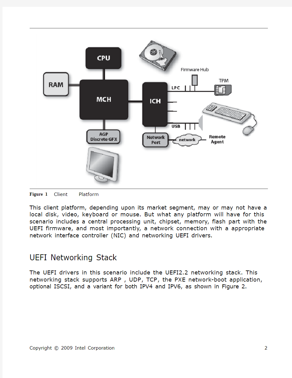
Figure 1 Client
This client platform, depending upon its market segment, may or may not have a local disk, video, keyboard or mouse. But what any platform will have for this scenario includes a central processing unit, chipset, memory, flash part with the UEFI firmware, and most importantly, a network connection with a appropriate network interface controller (NIC) and networking UEFI drivers.
UEFI Networking Stack
The UEFI drivers in this scenario include the UEFI2.2 networking stack. This networking stack supports ARP, UDP, TCP, the PXE network-boot application,
optional ISCSI, and a variant for both IPV4 and IPV6, as shown in Figure 2.
Figure 2 Networking Stack
The diagram in Figure 2, from the bottom up, shows the hardware elements of the stack, such as the Universal Network Device Interface (UNDI), which abstracts the NIC send and receive datagram capability. This raw UNDI interface is abstracted via the Simple Network Protocol (SNP). The SNP, in turn, is abstracted by the Managed Network Protocol (MNP). As opposed to the earlier EFI network technology wherein only one application could open the SNP exclusively, the MNP allows for many concurrent listeners, thus allowing for several services to concurrently operate. What this means is that an Extensible Authentication Protocol (EAP) handler looking for layer 2 messages can coexist with both the UEFI IP4 and UEFI IP6 stack applications such as PXE boot and ISCSI.
The multiple-consumer nature of the MNP and the UEFI2 nature stack is important because many of the network-based provisioning scenarios are “blended.” The blending is borne of the fact that the scenario may entail some network authentication action as a preamble in order to allow the client onto the provisioning network, then an ISCSI mount in order to have a file system, and finally, a PXE boot such that an installer or test application can be downloaded. The latter UEFI application, in turn, will access to the file system on ISCSI while performing its own network-specific file operations.
Securing the Network
Because of the expanded natures of local area networks (LANs), wide-area networks (WANs), and networks of networks, such as the Internet, providing secure interaction among agents on the wire is imperative. One of these scenarios is shown in Figure 3, which elucidates a network download and the salient trust elements.
Boot
Figure 3 PXE
The notable aspect of this download is the initial EAP transaction. Historically, PXE began with a DHCP discovery message in order to ascertain the location of the boot server. But corporate IT departments have some concerns with this former model. IT typically hosts the boot provisioning server, and the concept of a “bare-metal” machine joining their corporate network is a concern. With the advent of 802.1x controlled ports and EAP, though, the client machine can be configured
such that it must satisfy a challenge-response prior to joining the network, as shown in Figure 4. This entails the client responding to a set of EAP layer 2 messages from the switch, which in turn are transmitted to the authentication server via the well-known Radius protocol.
Figure 4 802.1x/EAP Challenge-Response
Once the client machine has been authenticated via the EAP challenge/response, it is allowed onto the network. UEFI 2.2 supports both the 802.1x state machine in the firmware and the ability to register a plurality of different EAP handlers. These handlers can include pre-shared key (PSK) methods, such as CHAP, and can be extended to more sophisticated single or mutual authentication methods based upon asymmetric cryptography like RSA, including but not limited to a Transport Layer Security (TLS) handshake.
As the needs arise, other network perimeter EAP methods can be included in the UEFI clients, such as EAP Kerberos or the Trusted Computer Group’s EAP Trusted Network Connect (TNC). The former is interesting as it will allow the UEFI Client to participate into an extant enterprise network topology, and the latter is useful since the pre-OS posture of the UEFI client, such as its code identity as described in the Trusted Platform Module’s (TPM) Platform Configuration Registers (PCR) can be used to assess the posture of the UEFI client prior to letting it on the network. EAP is at layer 2, so it works on IPV4 or IPV6 networks. After gaining access to the network, the UEFI client can attempt a DHCPv4 or DHCPv6-based network
discover request. The ability to do either or both is enabled via UEFI and its dual stack. With the imminent exhaustion of the 32-bit Internet Protocol version 4 addresses, deploying UEFI 2.2 firmware with Internet Protocol version 6 support is key. IPV6 opens up the address space to 128-bits. And as UEFI firmware proliferates to compute platforms beyond towards PC’s and servers (UEFI for appliances, non-standard platforms, and so on), the ability to support IPV6 networking in the pre-OS is imperative.
After the UEFI PXE application has negotiated with the boot server for a server name and IP address, it can commence the download of the boot image. In UEFI, the boot image isn’t the small 16-bit file of some tens of kilobytes as in conventional BIOS but is instead a fully-qualified Portable Executable Common Object File Format (PE/COFF) image. The UEFI executable is downloaded to the client machine for execution.
Now recall how earlier we mentioned that IT may set up EAP for authenticating the client such that a rogue UEFI machine may not wander onto IT networks. A similar concern emerges with respect to the downloaded executable. The UEFI client wants to defend itself from any random bits on the network, especially given the distributed nature of today’s topologies, rogue wireless access points, and other venues for Man-in-the-Middle (MITM) attacks on the wire to occur.
The credential listed in Figure 4 would be something like an x509v2 certificate with a public verification key. The UEFI firmware uses the public key to verify the digital signature of the boot image in order to ensure that it hasn’t been modified by an unauthorized party during transit. UEFI2.2 introduced the use of Authenticode image signing such that the trust hierarchy can be flat or nested, allowing for various deployment options. In addition, the rich UEFI network stack allows for the firmware to check for certificate expiry for possible future revocation models (such as if the private key associated with the public key in the certificate has been divulged).
A sample certificate is shown in Figure 5
Figure 5 Example of a x509v2 digital certificate
Important fields include name information, the expiry date, and the signature. The signature in this example includes an SHA-1 digest of the data signed by a 2048-bit RSA asymmetric key. This example also includes a 2-level deep hierarchy where the authority in this case is Intel.
To bring all of these elements together, Figure 6 shows a flow-chart of the end-to-end process of booting. It includes the actions of both the boot server and client machine.
Figure 6 Overall Boot Flow
Figure 6 shows the overall network boot process. The first portion is the use of the Dynamic Host Configuration Protocol (DHCP) by the UEFI client in order to query the network for both an IP address and the availability of a boot server. The DHCP offer from the client and response from server are important in that the client tells the boot server the “type” of client, such as x64 UEFI. The server, in turn, responds if it can support providing images to the machine.
One important image that can be downloaded to the platform is the UEFI Shell. Given that there are a plurality of activities that need to occur during provisioning, such as downloading additional files to image on the disk, activating certain devices like TPMs, the shell can be used to orchestrate their invocation and pass results.
For more information about the UEFI Shell, please refer to the book Harnessing the UEFI Shell by Michael Rothman, Tim Lewis, Vincent Zimmer and Robert Hale.
About the Authors
Michael Rothman is a Senior Staff Engineer in the Software and Services Group at Intel and has nearly 20 years of operating system and embedded software development experience. His career has spanned the gamut of being the development lead for the PC DOS product, development on retail and embedded versions of DOS and OS/2, and working on both legacy and UEFI BIOS codebases.
Tim Lewis is the Chief Architect at Phoenix Technologies Ltd. for all UEFI-based products, with over 20 years experience in BIOS development. He currently serves on the UEFI board of directors.
Vincent Zimmer is a Principal Engineer in the Software and Services Group at Intel. Vincent has over 17 years experience in embedded software spanning real-time control, RAID, and BIOS/boot firmware. In addition to contributing to UEFI implementations on https://www.wendangku.net/doc/6a14310492.html,, Vincent has written specifications in the UEFI Forum, Intel Framework, the Internet Engineering Task Force (IETF) and the Trusted Computing Group.
Robert Hale is a Principal Engineer in the Software and Services Group at Intel. After stints doing real-time operating systems and networking, he has been a BIOS developer since 1986. Robert was one of the original Framework (now PI) architects, leading a firmware team that deployed the first Framework-based product for EFI.
Copyright ? 2009 Intel Corporation. All rights reserved.
This article is based on material found in book Harnessing the UEFI Shell by Michael Rothman, Tim Lewis, Vincent Zimmer and Robert Hale. Visit the Intel Press web site to learn more about this book: https://www.wendangku.net/doc/6a14310492.html,/intelpress/sum_eshl.htm
No part of this publication may be reproduced, stored in a retrieval system
or transmitted in any form or by any means, electronic, mechanical,
photocopying, recording, scanning or otherwise, except as permitted under
Sections 107 or 108 of the 1976 United States Copyright Act, without either
the prior written permission of the Publisher, or authorization through
payment of the appropriate per-copy fee to the Copyright Clearance Center,
222 Rosewood Drive, Danvers, MA 01923, (978) 750-8400, fax (978) 750-
4744. Requests to the Publisher for permission should be addressed to the
Publisher, Intel Press, Intel Corporation, 2111 NE 25 Avenue, JF3-330,
Hillsboro, OR 97124-5961. E-mail: intelpress@https://www.wendangku.net/doc/6a14310492.html, .