不同EGR系统对共轨柴油机影响的试验和计算研究

Copyright ? 2009 SAE International
ABSTRACT
Different EGR system layouts (a Long Route, a Short Route, and a combination of the two) were evaluated by means of both numerical simulation and experimental tests.
In particular, a one-dimensional fluid-dynamic engine model was built in order to evaluate the potential of a Long Route EGR system as well as the potential of different EGR combinations between Long and Short Route.
By means of the one-dimensional model, used as a virtual test bench, the estimations of the NOx emissions, based on the Extended Zeldovich Mechanism (EZM), for the different solutions, were compared and valuable information for the calibration of the coordinated EGR LR, EGR SR and Variable Geometry Turbine (VGT) control systems was obtained.
Using the Long Route EGR layout, or a proper combination of LR and SR, substantial reductions of the NOx emissions both under steady state and transient operating conditions were achieved, while the numerical simulation allowed obtaining some fundamental knowledge for controlling the EGR flow rate more accurately.
INTRODUCTION
Exhaust Gas Recirculation (EGR) nowadays plays a fundamental role for automotive diesel engines in achieving emission figures able to comply with increasingly tightening regulations, due to the severe difficulties that have to be faced for the development of cost-effective NOx aftertreatment systems [1], [2]. System architectures that can be used in order to introduce EGR into engine cylinders through an external circuit include both Short Route (SR) and Long Route (LR) layouts, as well as “hybrid” or dual loop layouts obtained by a combination of the two. While in the Short Route EGR system a fraction of the exhaust gas is diverted from the exhaust manifold - upstream of the turbine - to the intake manifold – downstream of the compressor (see Figure 1), in the Long Route EGR the exhaust gas portion to be recycled is taken from the main exhaust flow downstream of the turbine and of the aftertreatment system, and it is recirculated upstream of the compressor (see Figure 2). The SR and LR architectures can also be combined together, thus obtaining what is usually called a hybrid or dual loop system (see Figure 3).
Although the SR architecture has been so far the preferred solution for passenger car diesel engines, the increasing diffusion of Diesel Particulate Filters (which will become mandatory to achieve emission levels complying with Euro 5 regulations) and moreover their Close Coupled mounting, has encouraged the use of LR systems [3-6], since the recirculation of a “clean” exhaust flow substantially reduces the drawbacks related to compressor wheel damages and charge air cooler fouling, and greatly simplify the “plumbing” of the circuit with an acceptable permeability level.
The LR system offers the opportunities of achieving higher EGR rates while maintaining low intake temperatures as well as of attaining a more uniform
2009-01-0672
Experimental and Computational Analysis of Different EGR Systems for a
Common Rail Passenger Car Diesel Engine
F. Millo, C.V. Ferraro and M. Gianoglio Bernardi
Politecnico di Torino
S. Barbero and P. Pasero
General Motors Powertrain Europe SAE Int. J. Engines | Volume 2 | Issue 1527
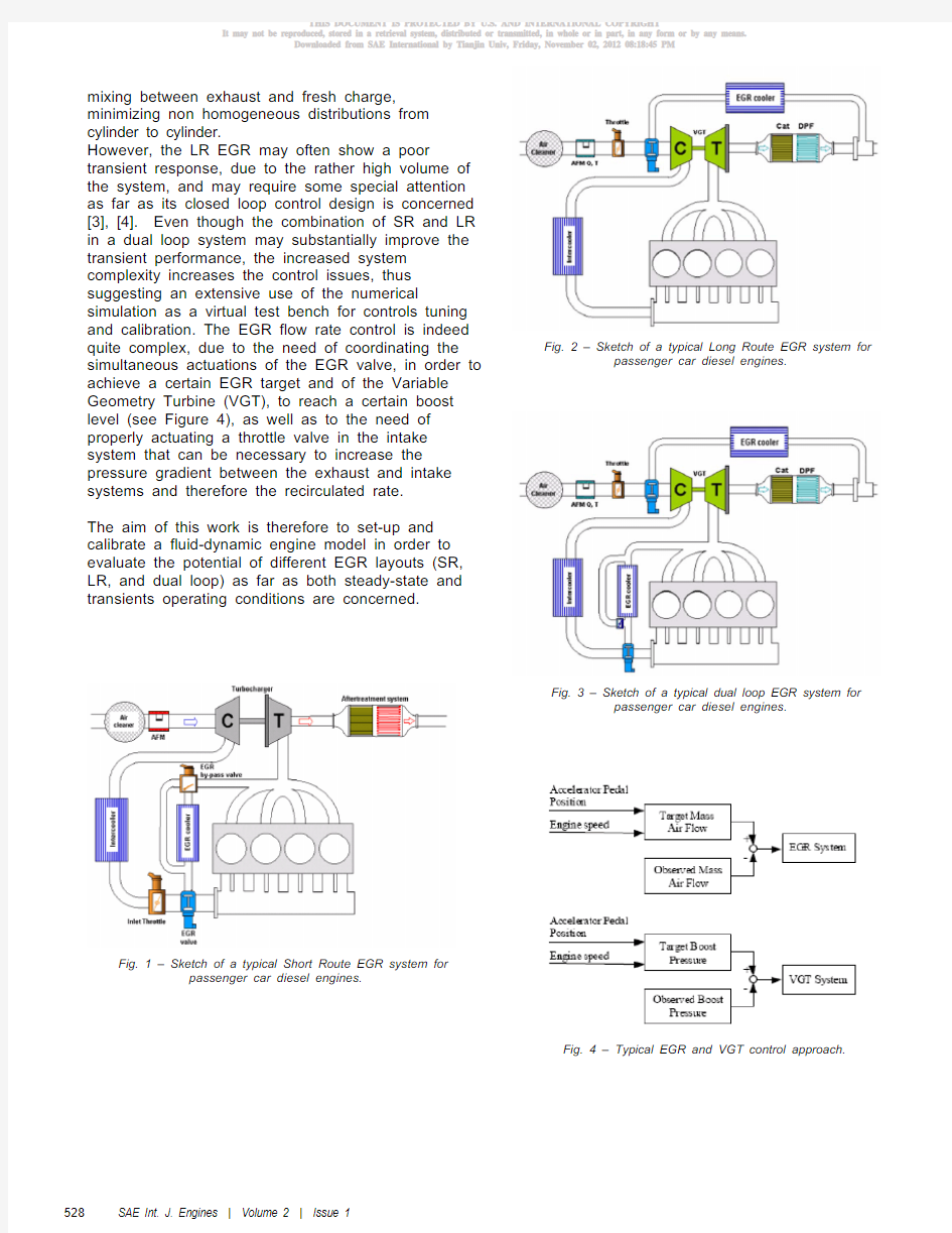
mixing between exhaust and fresh charge, minimizing non homogeneous distributions from cylinder to cylinder.
However, the LR EGR may often show a poor transient response, due to the rather high volume of the system, and may require some special attention as far as its closed loop control design is concerned [3], [4]. Even though the combination of SR and LR in a dual loop system may substantially improve the transient performance, the increased system complexity increases the control issues, thus suggesting an extensive use of the numerical simulation as a virtual test bench for controls tuning and calibration. The EGR flow rate control is indeed quite complex, due to the need of coordinating the simultaneous actuations of the EGR valve, in order to achieve a certain EGR target and of the Variable Geometry Turbine (VGT), to reach a certain boost level (see Figure 4), as well as to the need of properly actuating a throttle valve in the intake system that can be necessary to increase the pressure gradient between the exhaust and intake systems and therefore the recirculated rate.
The aim of this work is therefore to set-up and calibrate a fluid-dynamic engine model in order to evaluate the potential of different EGR layouts (SR, LR, and dual loop) as far as both steady-state and transients operating conditions are concerned.
Fig. 1 – Sketch of a typical Short Route EGR system for
passenger car diesel engines.
Fig. 2 – Sketch of a typical Long Route EGR system for passenger car diesel engines.
Fig. 3 – Sketch of a typical dual loop EGR system for passenger car diesel engines.
Fig. 4 – Typical EGR and VGT control approach.
SAE Int. J. Engines | Volume 2 | Issue 1 528
ENGINE CHARACTERISTICS AND EXPERIMENTAL SET- UP
A Common Rail turbocharged 2.0 liters displacement diesel engine was selected for this analysis, the main features of which are listed in Table 1.
The engine, which was originally equipped with a SR EGR system as shown in Figure 1, was modified by adding a LR EGR circuit, thus obtaining a dual loop system as shown in Figure 3.
All experimental tests on the reference engine were carried out on an AVL high-dynamic test bed, which was recently set-up at ICE Advanced Laboratory of Politecnico di Torino.
Engine type DI Turbocharged Diesel
EURO4
Displacement 1910
cm3
Bore x stroke 82.0mm x 90.4mm Compression ratio 17.5:1 Turbocharger Single-stage with VGT
Fuel injection system Common Rail 2nd gen. CRI2.2 – 1600bar
Maximum power and
torque 110kW @ 4000rpm 320Nm @ 2000rpm
Table 1 – Main design features of the test engine.
The test rig is equipped with an ELIN AVL APA 100 cradle-mounted dynamometer featuring maximum torque and power of 525 Nm and 200 kW, respectively, as well as a maximum speed of 12000 rpm. The facility is capable of realizing full four-quadrant operation with high speed and torque dynamics, including simulation of zero torque and gear shifting oscillations in the drivetrain.
The instantaneous fuel consumption was measured through an AVL KMA 4000 system, which is based on a servo-controlled positive displacement counter and can perform measurements over a range of 0.02 – 380 kg/h with a reading accuracy of 0.1%.
As far as the exhaust gas analysis is concerned, the test facility is equipped with a Pierburg AVL AMA 4000 raw exhaust-gas analyzer, which is made up of two analyzer groups which can be operated in parallel, both allowing the measurements of the concentrations of unburned hydrocarbons (HC), nitrogen oxides (NOx), CO, CO2 and O2. The measurement of pollutant levels can therefore be carried out simultaneously in two different locations of the engine intake and exhaust systems (for instance, in the exhaust manifold upstream of the aftertreatment system and in the intake manifold, in order to evaluate the EGR ratio). Finally, as far as smoke emissions are concerned, the dynamic test bed is equipped with an AVL 415S smokemeter for steady state measurements and with an AVL 439S opacimeter for transient measurements.
Glow plug piezoresistive pressure transducers, coupled with a high-resolution crankshaft encoder, allow in-cylinder pressure measurement in all cylinders. Moreover, gas temperatures and pressures in the most important locations of the exhaust and intake system of the engine (i.e. upstream and downstream of the compressor and turbine, of air and EGR coolers, etc.) are measured by means of K-type thermocouples and piezoresistive pressure transducers respectively.
All of the described measurement devices are controlled by PUMA Open 1.3.2 automation system, which also includes ISAC 400 software for the simulation of vehicle (road load, road gradient and moments of inertia of the driveline components that are not physically present on the test bed) and driver behavior (use of clutch, accelerator pedal and gear shifting), thus allowing the user to reproduce the driving cycles which are usually carried out on the whole vehicle on the chassis dynamometer. PRELIMINARY EXPERIMENTAL TESTS
Some preliminary experimental tests were initially carried out by running the engine over the New European Driving Cycle (NEDC), and simulating the coupling with an European Sedan passenger car, featuring a 1700 kg IW (see Figure 5), in order to provide validation data for the engine model as far as transient operating conditions are concerned. Afterwards, 31 steady state operating points, as representative of the engine usage over NEDC (see Fig. 5 and Table 2), were selected for experimental tests in order to provide validation data for the engine model as far as steady-state operating conditions are concerned.
SETTING UP THE ENGINE MODEL
Simulations were carried out using GT-Power, a one dimensional fluid-dynamic code developed by Gamma Technologies for engine performance prediction. The general features of the code are described in detail in [7], [8], [9], while the model construction and the validation process will be briefly summarized here below.
The baseline model construction requires a careful and detailed schematization of the engine and of the intake and exhaust system geometry, as well as accurate and extensive experimental data, which have to be carefully analyzed to properly set heat
SAE Int. J. Engines | Volume 2 | Issue 1529
Fig. 5 – ECE-EUDC operating points and model validation
points.
transfer and friction loss coefficients, combustion heat release profiles and engine friction estimation. In particular, as far as the combustion model is concerned, the heat release profiles obtained by the analysis of experimental in-cylinder pressure traces were used for the baseline model, while engine friction losses were evaluated through motoring tests. The heat exchange process inside the intake charge coolers (intercooler, short route and long route EGR coolers) was modeled by means of experimentally derived performance maps providing coolers effectiveness as a function of gas flow rate. The pressure drop across the coolers was calibrated by means of the experimental data acquired during experimental steady state tests.
The simulation results were then compared with the experimental results under both steady-state and transient operating conditions, as shown in the following paragraphs.
MODEL VALIDATION: STEADY STATE
The closed loop engine controls for VGT rack position, injected fuel rate and EGR valve position were simulated by means of three PID controllers aiming to reach target values of intake manifold pressure, BMEP and air mass flow rate respectively. Comparisons between experimental and simulated values of B SFC and O2 concentration in the intake manifold are shown in Figures 6 and 7 respectively as an example of the model validation process for part load operating conditions.
The agreement between simulated and measured data is more than satisfactory and the model could therefore be regarded as calibrated with reasonable accuracy as far as steady-state operating conditions are concerned. Speed [rpm] bmep [bar]
900 idle
1
2
3
1000
4
1
2
3
1250
4
1
2
3
4
5
1500
6
1
2
3
4
5
2000
6
4
5
6
8
2500
9
4
5
6
7
3000
8
Table 2 – Steady state engine operating points selected
for experimental tests for model validation.
MODEL VALIDATION: TRANSIENT
Further validations were then performed for transient
operating conditions. The comparison between
measured and simulated injected fuel rate over a
portion of the NEDC is shown in Fig. 8 as an
example, while measured and simulated O2
SAE Int. J. Engines | Volume 2 | Issue 1
530
Fig. 6 – Comparison between experimental and simulation results for brake specific fuel consumption under part load operating
conditions (2000 rpm – 1 ÷ 6 bar BMEP).
Fig. 7 – Comparison between experimental and simulation results for oxygen concentration in the intake manifold under part load operating conditions (2000 rpm – 1 ÷ 6 bar
BMEP).
concentrations in the intake manifold and NO X exhaust emissions are shown in Fig. 9 and 10 respectively, again demonstrating a good agreement between the model predictions and the experimental data also under transient operating conditions, although some remarkable differences between simulated and experimental results can be observed in Fig. 8 and 10 during gear shifts.However, these discrepancies can be mainly attributed to an incorrect setting of the PID controllers used to simulate the driver’s behavior on the test rig as far as clutch engagement phases during gear shifts are concerned, leading to abrupt actions on the accelerator pedal and thus to fuel and NOx peaks, which cannot be considered as representative of real driving cycle conditions and were therefore disregarded as far as the driver behavior
reproduction in the simulation model is concerned.
Fig. 8 – Comparison between experimental and simulation results for fuel consumption over the first 150 seconds of
the ECE portion of the NEDC.
Fig. 9 – Comparison between experimental and simulation results for oxygen concentration in the intake manifold over the first 150 seconds of the ECE portion of the NEDC.
Fig. 10 – Comparison between experimental and
simulation results for exhaust NOx emissions over the first
150 seconds of the ECE portion of the NEDC.
SAE Int. J. Engines | Volume 2 | Issue 1
531
EVALUATION OF THE PERFORMANCE OF DIFFERENT EGR LAYOUTS UNDER STEADY STATE OPERATING CONDITIONS
After the above mentioned validation process, the one dimensional engine model was then used as a virtual test bench to compare the performance of the Short Route and Long Route EGR layouts under steady-state operating conditions. Although the same tests can be performed experimentally, the use of the numerical simulation may provide indeed some
additional information concerning quantities which
cannot be measured (such as for instance instantaneous gas temperatures or mass flows) and may therefore be extremely helpful in gaining a better knowledge for controlling the EGR flow rate more accurately and containing NOx emissions more effectively.
In order to evaluate the LR versus SR performance some EGR sweeps (i.e. variations of the EGR rate while all other engine parameters were maintained at a constant value) were carried out at different engine loads and speeds, as shown in Figures 11-17.
As expected, the LR layout results to be more effective for NOx reduction in comparison with the SR layout (see Figure 11), allowing the achievement of lower NOx levels for a certain EGR rate, thanks to the lower intake temperatures that can be maintained (Figure 12). However, the NOx advantage shown by the LR EGR for a certain recirculated rate tends to decrease at higher EGR levels, since, due to lower intake temperatures, higher fresh air mass flows can be intaken and higher oxygen concentrations in the intake manifold can be obtained for a certain EGR rate (see Figure 13).
As the recirculated gas flow increases, the B SFC increases as well (see Fig. 14), but with slightly higher values for the SR layout than for the LR layout (a maximum difference of about 2% at 25% EGR rate can be noticed in Figure 14).
More substantial B SFC advantages may be observed for a certain NOx specific emissions level, as shown in Figure 15, where the BSFC vs. BSNOx trade-off is reported. Moreover, a different B SFC trend can also be noticed both in Fig. 14 and in Fig. 15: while the SR shows a constantly increasing trend with the EGR rate (see Fig. 14), an abrupt slope change can be noticed in the LR trend for a 25% EGR rate. This sudden worsening of the LR BSFC is due to the need of introducing a substantial throttling at engine intake in order to further increase the EGR rate, since the pressure gradient for the LR layout would otherwise be insufficient to obtain high EGR flows: the throttling effect can be clearly seen in Figure 16, where the Pumping Mean Effective Pressure PMEP starts to rise for the LR as EGR rates exceed 25%, as well as in Figure 17 where the engine indicated efficiency drops for the LR above 25% EGR rates.
The negligible differences in pumping work for the LR and SR architectures shown in Fig. 16 may deserve some further investigation, since the LR system could be expected to provide some advantages in pumping due to a better efficiency of the turbine, that can be operated with a reduced closure of the rack position.
However, turbocharger data reported in Table 3 for the 25% EGR rate operating condition clearly show that the better turbine and compressor efficiencies that can be achieved by the LR system are almost completely nullified by the higher power requested by the compressor due to the higher mass flow rate to be compressed and to the higher inlet temperature, thus resulting in almost identical values of the engine backpressure.
LR
SR
Efficiency 62 55 [%] Power 0.72 0.50 [kW]
Back Press./Boost Press. Ratio
1.18 1.19 [-]
T u r b i n e
Rack Position
(0% fully closed, 100% fully open)
21 15 [%]
Efficiency 52 50 [%] Specific Work 24.4 23.4 [kJ/kg]C o m p r e s s o r
Inlet Temperature
314
296
[K]
Table 3 – Comparison between Short Route and Long
Route turbocharger operating conditions @ 1500 rpm / 2
bar of BMEP / 25% EGR.
In conclusion, the numerical simulation allows also to point out that the better indicated efficiency of the LR system can be mainly attributed to the lower values of the instantaneous rate of heat transfer from gases to cylinder walls (see Fig. 18), thanks to the reduced combustion temperatures.
EVALUATION OF DIFFERENT LAYOUTS AND CONTROLS UNDER TRANSIENT OPERATING CONDITIONS
Since the EGR control in transient conditions is one of the most critical key points in the engine calibration process, the engine model was also used as a virtual test bench in order to achieve a preliminary tuning of the EGR rate closed loop strategies for the different system architectures.
The two EGR layouts were then compared over three different types of transients:
x EGR valve step; x Load step;
x ECE/EUDC driving cycles.
SAE Int. J. Engines | Volume 2 | Issue 1
532
Fig. 11 – Comparison between different EGR layouts (EGR SR and EGR LR): NO X emissions vs. EGR rate @
1500 rpm / 2 bar of BMEP.
Fig. 12 – Comparison between different EGR layouts (EGR SR and EGR LR): intake manifold temperature vs.
EGR rate @ 1500 rpm / 2 bar of BMEP.
Fig. 13 – Comparison between different EGR layouts
(EGR SR and EGR LR): Oxygen concentration in the intake manifold vs. EGR rate @ 1500 rpm / 2 bar of BMEP.
Fig. 14 – Comparison between different EGR layouts (EGR SR and EGR LR): BSFC vs. EGR rate @ 1500 rpm /
2 bar of BMEP.
Fig. 15 – Comparison between different EGR layouts (EGR SR and EGR LR): NO X emissions vs. BSFC trade-off @ 1500 rpm / 2 bar of BMEP.
Fig. 16 – Comparison between different EGR layouts (EGR SR and EGR LR): PMEP/BMEP ratio vs. EGR rate
@ 1500 rpm / 2 bar of BMEP.
SAE Int. J. Engines | Volume 2 | Issue 1533
Fig. 17 – Comparison between different EGR layouts (EGR SR and EGR LR): engine indicated efficiency vs.
EGR rate @ 1500 rpm / 2 bar of BMEP.
Fig. 18 – Comparison between different EGR layouts (EGR SR and EGR LR): heat transfer to total fuel energy ratio vs. EGR rate @ 1500 rpm / 2 bar of BMEP.
Fig.19 – Comparison between different EGR layouts (EGR SR, LR and dual loop with 20% SR / 80%): analysis of the system response to a sudden opening/closing EGR valve
step. EGR valve step test
The system response to an EGR valve step opening and closing event is shown in Figure 19.
As expected, the SR architecture shows a faster response in comparison with the LR, which on the contrary reacts with a certain delay, due to the large volume of fluid which is trapped between the EGR valve and the intake manifold (the ratio between the LR circuit volume and the SR circuit volume is about 4). However, after the initial fast increase of the EGR rate, the SR system reaches the steady state value with a rise which is remarkably slower than the LR, since the EGR flow increase is hindered by the boost control strategy: due to the reduced exhaust mass flow through the turbine as the EGR valve is opened, the VGT closed loop control reacts by closing the turbine rack position, aiming to maintain the target boost pressure level. On the other hand, the increase of the intake manifold pressure reduces the pressure difference across the EGR valve, thus slowing the EGR rate rise.
On the contrary, the LR system response, after a longer initial delay, shows a rapid rise to the steady state value.
A dual loop system may be particularly helpful in this case, allowing a remarkable reduction of the drawbacks typical of each of the two architectures: the response delay can be minimized (thanks to the SR recirculation) and a faster rise to the steady state value can be achieved (thanks to LR recirculation), as shown in Figure 19 for a mixed loop solution (80% LR / 20% SR).
Load step test
The system response to a load step when fuel amount is suddenly increased is shown in Figures 20-25. The EGR valve was controlled both with a conventional Mass Air Flow (MAF) based logic (using the same look-up table of the mass air flow for both Long Route and Short Route systems) and with a new intake manifold O2 concentration based technique (using the same look-up table of the intake manifold oxygen concentration for both Long Route and Short Route systems). The VGT nozzle was controlled independently to match the target boost pressure level. It should be pointed out that, since the MAF control strategy goal is to reach a target air mass flow rate, the steady state values of oxygen concentration at the beginning and at the end of the load step are higher for the SR layout than for the LR layout (see Figure 21), because in the SR layout the average density of the recirculated gas is lower (due to the higher temperatures). These differences result in turn into higher NOx emissions at steady state conditions for the SR system (Figure 22).
SAE Int. J. Engines | Volume 2 | Issue 1 534
Fig. 20 – Comparison between SR and LR EGR systems (with closed loop MAF control) for EGR percentage over a
load step
Fig. 21 – Comparison between SR and LR EGR systems (with closed loop MAF control) for oxygen concentration in the intake manifold over a load step.
Fig. 22 – Comparison between SR and LR EGR systems (with closed loop MAF control) for exhaust NOx emissions
over a load step.
Fig. 23 – Comparison between SR and LR EGR systems (with closed loop O2 control) for EGR percentage over a
load step.
Fig. 24 – Comparison between SR and LR EGR systems (with closed loop O2 control) for oxygen concentration in the intake manifold over a load step.
Fig. 25 – Comparison between SR and LR EGR systems (with closed loop O2 control) for exhaust NOx emissions
over a load step.
SAE Int. J. Engines | Volume 2 | Issue 1535
As far as the transient response is concerned, the LR shows, as expected, a remarkable delay in the decrease of the EGR rate (Figure 20); moreover, an appreciable overshoot in O2 concentration can also be seen (Figure 21), which results in a notable detrimental effect on NOx emissions (Figure 22) compared to the steady state values.
As far as the control strategy based on oxygen concentration in the intake manifold is concerned (Figures 23, 24 and 25), it can be noticed that, although the steady state values of oxygen concentration at the beginning and at the end of the load step are identical in this case for the SR and for the LR layouts, (see Figure 24), NOx emissions at steady state are lower with the LR due to the lower
intake temperatures.
Moreover, while the O2 based control strategy seems to be extremely effective in reducing NOx emissions overshoots during the transient for the SR system, although it should be pointed out that some improvements could be expected for the LR system through a further optimization of the control strategy for this specific architecture, some appreciable NOx overshoot with the LR system could never be eliminated, since there is no way to drop down the oxygen concentration immediately after the fuel injection ramp, due to the large volume of gas with low EGR content trapped downstream of the EGR valve that must be ingested by the engine after the EGR valve actuation.
ECE/EUDC portions tests
Finally, the engine model was used to test and compare the performance of both the two EGR layouts under transient operating conditions such as those experienced by the engine during the NEDC.
This comparison was carried out using the O2 control strategy, since, as reported in [10] and shown also in the previous paragraph, it shows a better performance under transient conditions.
The results obtained during the first portion (60 s) of the EUDC are shown in Figure 26 and 27: as one can see, the LR system presents a remarkable advantage in terms of NOx cumulative emissions if compared with the SR system (with reductions up to 16% for the considered cycle segment). Nevertheless, the slow system response causes, during the acceleration ramps, some undesirable nitrogen oxides overshoots, as shown in Figure 26.
One possible solution to this drawback is the use of a dual loop system, which may improve the system response during transients (thanks to the SR better performance) while maintaining remarkable advantages during steady state or slow varying operating conditions, due to its lower intake manifold temperatures (thanks to LR behavior).
Fig. 26 – Comparison between SR and LR EGR systems with closed loop O2 control for exhaust NOx emissions
over the first 60 s of the EUDC.
Fig. 27 – Comparison between SR and LR EGR systems with closed loop O2 control for normalized NOx cumulative emissions over the first 60 s of the EUDC.
Fig. 28 – Comparison between LR and mixed loop EGR systems with closed loop O2 control for exhaust NOx emissions over the first 60 s of the EUDC.
NO X overshoot
NO X overshoots
reduction
SAE Int. J. Engines | Volume 2 | Issue 1 536
Fig. 29 – Comparison between SR, LR and mixed loop
EGR systems with closed loop O2 control for normalized
NOx cumulative emissions over the first 60 s of the EUDC.
A remarkable reduction of the NOx overshoots during acceleration ramps can be observed in Fig. 28 and a further cumulative NO X emissions benefit up to 4% for the considered cycle segment can be noticed in Fig. 29, thus demonstrating the potential of the dual loop solution.
CONCLUSIONS
Different EGR system layouts (a Long Route, a Short Route, and a combination of the two) were evaluated by means of both numerical simulation and experimental tests.
By means of a fluid-dynamic one-dimensional model, used as a virtual test bench, the estimations of the NOx emissions for the different solutions were compared and valuable information for the calibration of the coordinated EGR LR, EGR SR and VGT control systems was obtained.
Using the Long Route EGR layout, or a proper combination of LR and SR, substantial reductions of the NOx emissions both under steady-state and transient operating conditions were achieved, while the numerical simulation allowed obtaining some fundamental knowledge for controlling the EGR flow rate more accurately.
ACKNOWLEDGMENTS
The authors wish to thank Dr. Paolo Ferrero Giacominetto (Politecnico di Torino) for his helpful support during the experimental tests. REFERENCES
1. Johnson, T. V.: “Diesel Emission Control in
Review”, SAE Paper 2006-01-0030, 2006.
2. Cooper, B., Penny, I., B easley, M., Greaney, A.
and Crump, J.: “Advanced Diesel Technology to
Achieve Tier 2 Bin 5 Emissions Compliance in
US Light-Duty Diesel Applications”, SAE Paper
2006-01-1145, 2006.
3. Mueller, V., Christmann, R., Gheorghiu, V. and
Muenz, S.: “System Structure and Controller
Concept for an Advanced Turbocharger/EGR
System for a Turbocharged Passcar Diesel
Engine”, SAE Paper2005-01-3888, 2005.
4. Shutty, J., B enali, H., Daeubler, L. and Traver,
M.: “Air System Control for Advanced Diesel
Engines”, SAE Paper 2007-01-0970, 2007.
5. Vítek, O., Macek, J., Polá?ek, M., Schmerbeck,
S. and Kammerdiener, T.: “Comparison of
Different EGR Solutions”, SAE Paper 2008-01-
0206, 2008.
6. Lujan, J.M., Pla, B., Moroz, S. and Bourgoin, G.:
“Effect of Low Pressure EGR on gas exchange
process and turbocharging of a H SDI engine”,
Thiesel 2008 Conference on Thermo-Fluid
Dynamic Processes in Diesel Engines, Valencia,
Spain, 2008.
7. Gamma Technologies Inc.: “GT-POWER User’s
Manual”, 2006.
8. Morel, T., Keribar, R., Leonard, A.: “Virtual
Engine/Powertrain/Vehicle Simulation Tool Solves Complex Interacting System Issues”, SAE
Paper 2003-01-0372, 2003.
9. Keribar, R., Ciesla, C. R., Morel, T:
“Engine/Powertrain/Vehicle Modeling Tool Applicable to all Stages of the Design Process”,
SAE Paper 2000-01-0934, 2000.
CONTACT
Federico Millo
Dipartimento di Energetica, Politecnico di Torino
C.so Duca degli Abruzzi, 24
10129, Turin, ITALY
phone: 39-011-0904517
fax: 39-011-0904599
e-mail: https://www.wendangku.net/doc/7317097934.html,lo@polito.it;
10. Millo, F., Pautasso, E., Pasero, P., and Barbero,
S. et al., “An Experimental and Numerical Study
of an Advanced EGR Control System for
Automotive Diesel Engine” SAE Int. J. Engines
1(1): 188-197, 2008.
SAE Int. J. Engines | Volume 2 | Issue 1537
DEFINITIONS, ACRONYMS, ABBREVIATIONS BMEP Brake Mean Effective Pressure BSFC Brake Specific Fuel Consumption
BSNOx ECE Brake Specific Nitrogen Oxides Economic Commission for Europe (urban driving cycle)
ECU Electronic Control Unit EGR Exhaust Gas Recirculation
EUDC EZM Extra Urban Driving Cycle Extended Zeldovich Mechanism
ICE Internal Combustion Engine
IW LR Inertial Weight Long Route EGR
MAF Mass Air Flow
NEDC New European Driving Cycle
NOx PMEP SR Nitrogen Oxides
Pumping Mean Effective Pressure Short Route EGR
VGT Variable Geometry Turbine SAE Int. J. Engines | Volume 2 | Issue 1
538
柴油机尾气后处理技术基础介绍
柴油机尾气后处理技术
基础开发室性能组
李兴民 2009.4
内容
尾气后处理技术简介 柴油机尾气的组成 后处理基础知识 典型后处理布置方案
DEUTZ (DALIAN) ENGINE CO.,LTD
尾气后处理技术简介
为什么要采用尾气后处理技术? 为了满足越来越苛刻的环保法 规要求,仅仅依靠发动机本体 的技术措施已经不能满足法规 的要求,专门针对发动机尾气 采用物理、化学方法进行净化 处理的方法叫做发动机尾气后 处理技术
DEUTZ (DALIAN) ENGINE CO.,LTD
排放法规
2 (8%)
cu rve
8 (9%) 10 (8%)
Torque
Fu ll l oa d
6 (5%)
4 (10%) 75% load
12 (5%)
5 (5%)
3 (10%) 50% lo ad
13 (5%)
7 (5%)
9 (10%)
25% load
11 (5%)
1 (15%) idle
250
A
B
C
Engine speed
100 Torque [%]
200
50
150
0
Engine speed [%]
100
-50
50
-100
0 0
Urban
600
Rural Time [sec]
-150 1200 Motorway 1800
DEUTZ (DALIAN) ENGINE CO.,LTD
柴油机共轨系统
柴油机共轨系统 [来源:本网讯 2006/12/26] (日)伊藤泶次古田克则 【摘要】虽然柴油机热效率高,但排放法规的强度也在逐年增加。为此,近年来,具有高度柔性控制的、能进行超高压喷射的共轨系统已逐渐成为主流。介绍了共轨系统的结构、运行、特性及其主要部件??供油泵和喷油器的技术和未来发展趋势。 1 前言 与汽油机相比,柴油机热效率高,也就是说在燃油耗方面占有优势,因此在热衷环保的欧洲,柴油车占据汽车总产量的40%。另一方面,从防止大气污染的观点出发,颗粒(PM)和NOx的排放法规日趋严格,为了应对严格的排放法规,就必须实现燃油的高压喷射化和高度的喷油控制。 本文介绍在近年来可实现超高压喷射且控制自由度高的共轨喷油系统中供油泵和喷油器的 相关技术及其今后的发展动向。 2 共轨系统的构成、运行及特征 图1以日本DENSO公司第二代共轨系统为例示出了系统构成图,图2为系统构成部件的照片。其主要部件为:供油泵(生成高压燃油)、共轨(蓄积高压燃料)、喷油器(喷射燃油)以及控制这些部件的ECU和检测发动机运行状态的各种传感器。共轨系统是把在供油泵中生成的高压燃油蓄积在共轨中,然后通过喷油器中的执行器决定喷油开始和结束的电控燃油喷射系统。 图1 共轨系统构成 图2 系统构成部件 共轨系统的第一个特征是可以实现高压喷射而与发动机的转速无关,燃油喷雾可实现微粒化,从而促进燃油和空气的混合。因此可以实现更完全的燃烧,降低排气中的PM。为了实现这样的超高压喷射,产生高压的供油泵和蓄压的共轨必不可少。 第二个特征是实现了以往喷油系统不能实现的一个燃烧循环中的多次喷油,也提高了燃烧控制自由度。 第三个特征是由于可以修正喷油量,所以喷油精度高。因为考虑到燃油耗和降低排放,所以提高喷油器的喷油控制精度很重要。最近的研究表明,预喷射的喷油量越小,PM和NOx之间的折衷就越弱,为了实现高精度的多次喷射,装有高速执行器的喷油器不可或缺。 3 共轨系统构成部件 以下详细介绍构成上述共轨系统的基本部件:供油泵和喷油器。 3.1 供油泵 如图3的产品发展历史所示,第一代供油泵为卡车用的、以直列式喷油泵为基础的HP0泵,以及乘用车用的、以分配型喷油泵为基础的HP2泵。乘用车用的HP2泵利用电磁阀实现进油量调整,并采用了在分配型喷油泵上卓有成效的内凸轮。HP2泵最大压力为145 MPa,而比这更高的压力对传统的内凸轮方式而言已达到极限。为此,如图4所示,第二代供油泵把柱塞的驱动结构由滚子机构改为平面滑动机构,降低了驱动部分的面压,以实现180 MPa的超高压喷射。进而,作为对应180 MPa 超高压喷射的另一项技术,在采用上述压力供给机构的同时,在柱塞的滑动面上涂覆陶瓷涂层,进行
玉柴高压共轨系统维修柴油机培训材料
共轨系统概述BOSCH高压共轨技术 柴油共轨系统特性 传统柴油喷射系统其压力的产生与喷油量跟凸轮与柱塞联系在一起,喷油的压力随着发动机转速与喷油量的增加而增加。这种柴油系统已经无法满足日益严格的排放法规和降低油耗的愿望。 共轨系统(Common Rail Systems,简称CRS)将燃油在高压下贮存在蓄压器(高压油轨)中,从本质上克服了传统柴油机喷射系统的缺陷,其特性有: 喷油压力的产生不依赖于发动机转速与系统喷油量,可根据发动机不同的工况灵活控制喷射压力和油量,从而实现低转速高喷射压力,达到低速高扭矩,低排放及优化燃油经济性的目的。 通过电子控制单元算出理想的喷油量和喷油时间,再由喷油器精确地喷射,甚至多次喷射。更高的系统压力,更好的排放能力,更低的燃油消耗 柴油共轨系统组成 柴油共轨喷射系统由液力系统和电子控制系统构成。其中液力系统又分低压液力系统和高压液力系统。 液力系统 低压液力系统 —油箱 —输油泵 —燃油滤清器 —低压油管 高压液力系统 —高压泵 —高压油轨 —喷油器 —高压油管 电子控制系统(Electronic Diesel Control,简称EDC)
—传感器 —电控单元(Electronic Control Unit,简称ECU) —执行器,包括带电磁阀的喷油器、压力控制阀、预热塞控制单元、 增压压力调节器、废气循环调节器、节流阀等 —线束 其中,喷油器、高压泵、高压油轨、电控单元为柴油共轨系统四大核心的部件。 轨系统示意图 喷油器 喷油器是将燃油雾化并分布在发动机燃烧室的部件。共轨喷油器的喷油时刻和持续时间均经电控单元精确计算后给出信号,再由电磁阀控制。 高压泵 高压泵的作用是将燃油由低压状态通过柱塞将其压缩成高压状态,以满足系统和发动机对燃油喷射压力和喷油量的要求。 高压油轨 高压油轨的作用是存贮燃油,同时抑制由于高压泵供油和喷油器喷油产生的压力波动,确保系统压力稳定。高压油轨为各缸共同所有,其为共轨系统的标志。 电控单元 电控单元就像发动机的大脑,它收集发动机的运行工况参数,结合已存储的特性图谱进行计算处理,并把信号传递给执行器,实现发动机的运行控制、故障诊断等功能。
柴油机后处理净化技术
柴油机后处理净化技术 1.氧化催化转化器 氧化催化转化器是利用催化剂,象滤清器那样通过排气,将有害成分HC、CO、NOx进行化学反应转化为无害的CO2、H2O和N2的反应器。 减小污染物浓度的原理: 把一氧化碳(CO)、碳氢化合物(HC)和颗粒中的可溶性有机物SOF成分氧化成二氧化碳和水。 氧化催化转化器的结构: 主要由壳体、衬垫(减震层)、载体和催化剂涂层四个部分组成。 ①壳体通常为不锈钢材料,防止高温氧化脱落。 ②衬垫通常为陶瓷材料;隔热性、抗冲击性、密封性和高低温冲 击性优于金属网。 ③载体材料主要有蜂窝陶瓷载体和金属载体两种。 ④催化剂涂层。涂层(γ-Al2O3)+主催化剂(铂Pt、钯Pd) 2.NOx机外净化技术 (1)吸附催化还原法(LNT) 催化剂活性成分:贵金属和碱土金属 在富氧气氛下,用吸附剂MO先将NOx储存起来: 然后在贫氧的还原气氛下进行分解和还原,其反应如下:
(2)选择性催化还原(SCR) NOx的催化还原技术有:选择性非催化还原(SNCR)、非选择性催化还原(NSCR)和选择性催化还原(SCR)三种方式,其中以选择性催化还原(SCR)技术在柴油机上的研究最为广泛。 工作原理: 以NH3或者HC作为还原剂,在催化剂的作用下将NOx转化为无害的氮气(N2)和水蒸气(H2O)。 (3)等离子辅助催化还原(NTP) 机理:空气经过低温等离子体作用后,产生一系列氧化性极强的自由基(OH*、HO2*)、原子氧(O)、臭氧(O3)等强氧化物质,这些物质将发动机尾气中的NO氧化,并转化为NO2
3. 颗粒物机外净化技术 微粒捕集器(DPF )对颗粒物进行捕集是最可行的一种后处理技术。此外,也有使用等离子体净化技术和静电分离技术等法对颗粒物进行脱除。 (1)DPF 结构 陶瓷蜂窝载体 陶瓷纤维编织物 22O O ??→2O N NO N +??→+2N O NO O +??→+*N OH NO H +??→+2NO O NO +??→*222NO OH NO H O ++??→** 22NO HO NO OH +??→+323NO O NO +??→
浅谈柴油机高压共轨技术
浅谈柴油机高压共轨技术 浅谈柴油机高压共轨技术 一、高压共轨技术简介我们先来了解下传统柴油发动机燃油喷射 系统的局限性:传统柴油发动机燃油喷射系统的工作过程再按照一定是:柴油通过高压油泵提高油压后,喷入气缸燃的供油定时
和供油量通过喷油器, 烧室。在燃油喷射过程中,由于压力波动,存在二次喷油现象。由于二次喷油不可能完全燃烧,油耗于是增加了烟度和碳氢化合物的排放量, 每次喷射循环后高压油管内的残此外,也增高。尤其随之引起不稳定的喷射,压都会发生变化,严重时不仅喷在低转速区域容易产生上述现象,油不均匀,而且会发生间歇性不喷射现象。为随着发动机自动控制技术的发展和进步,了解决柴油机燃油压力变化所造成的燃油喷射现代柴油机采用了一种 高压共轨电控燃烧缺陷,燃油喷射技术,使柴油机的性能得到了全面提升。,柴油机在机械喷射、增压喷射和普通电喷后轨共。射高压喷高共现来几近年出了轨压电喷技术 是指在高压油泵、压力Rail)Common (- 1 - 传感器和电子控制单元(ECU)组成的闭环系统中,相比于一般的喷油系统,它的压力建立、喷射压力控制和喷油过程相互独立,并
可以灵活地控制。它是由高压油泵将高压燃油输送到公共供油管(Rail),通过公共供油管内的油压实现精确控制,使高压油管压力(Pressure)大小与发动机的转速无关,可 以大幅度减小柴油机供油压力随发动机转 速变化的程度。 另外,共轨喷油系统的高精度零部件的表面加工质量要求高,几何精度高,特殊要求多,其加工都是微米、亚纳米级的精度,代表了目前机械制造行业的最高加工水平。 二、高压共轨系统的组成和工作原理 2.1、高压共轨喷射系统组成 高压共轨喷射系统主要由高压油泵、共轨ECU管、电控喷油器、各种传感器和电控单元- 2 -
柴油机高压共轨电控燃油喷射技术介绍
柴油机高压共轨电控燃油喷射技术介绍 摘要:传统机械发动机的喷油系统凭借其可靠性、易维护性一直在不断地发展和使用。进入21世纪以来,随着人们对能源、环保的意识和要求日益提高,传统发动机的脉动喷油系统已经不能够满足现代发动机的要求。因此,现代发动机的共轨燃油喷射技术在避免了传统发动机缺点的基础上,得到了快速的发展,已经成为燃油喷射的主要发展趋势。为了更好的对高压共轨电控发动机燃油喷射系统的理解,现对高压共轨电控燃油喷射系统进行系统的介绍。 1 引言 随着世界各国工程机械、运输车辆等数量增加,柴油机排放的尾气已经成为对地球环境的主要污染原因之一,如何采取措施保护人类赖以生存的地球环境已是当务之急。我国从八十年代起相应制订了有关的标准,将环境保护作为大事来抓。与此同时,世界各国也已开始寻找和探究其他方法和采取其他有效的技术措施主动地减少和控制污染物的排放。共轨式电控燃油喷射技术正是从众多方法和措施中脱颖而出的一项较为成功的控制柴油机污染排放的新技术。 2 高压共轨电控燃油喷射技术发展过程 20世纪40年代电控共轨燃油喷射技术首先在航空发动机上应用,20世纪50年代在赛车发动机上广泛应用。20世纪90年代,柴油机的电控供油系统开始在实际应用中大量使用。主要有日本电装公司和丰田汽车公司ECD-U2系统、博世公司和D-C公司电控共轨式燃油喷射系统。 国外在柴油机电控高压共轨燃油喷射系统方面的研究开展得较早而且比较深入,有多种共轨系统已经投产,并与整车进行了匹配应用。日本电装公司的ECD-U2系统是电控高压共轨燃油喷射系统的典型代表,该系统还能实现预喷射和靴型喷射。 共轨喷射的发展大体经历了3个阶段,如表1所示。 从表1中可以看出:共轨喷射的最高喷射压力在不断提高,这样对于喷射品质的提高有着重要的意义。压力越高,燃料雾化越好,颗粒越小越均匀,燃烧越充分,经济性、动力性和排放性均好,但这对喷射系统的要求也越高;喷射的次数不断增加,可以实现满足发动机燃烧和排放的多次喷射,可以控制燃烧的不同阶段喷油量和喷油速率,使燃烧更充分,热效率提高;在最小稳定喷射量上,3个阶段的每次的喷射量在下降,这说明每次喷射时候可以使喷射更均匀、更细密,喷油和断油更干脆,反应灵敏,响应特性好,这样有利于燃烧,减少积炭的产生。
HW:柴油机后处理技术概述
当下常用柴油机后处理技术: 1SCR(Selective Catalytic Reduction选择性催化还原技术) 1.1NH3- SCR 1.1.1反应原理 使用尿素水溶液作为氨气来源,这种溶液尿素质量分数为32.5%,符合DIN V70070国际标准,市 场上也称之为“AdBlue”溶液。当尿素水溶液被喷射到排气管中后,与高温的废气混合,尿素水溶 液经过气化、热解和水解等一系列复杂的化学反应生成氨气和二氧化碳,简单可以分为两步。 第一步: 热解反应 CO(NH2)2→加热→NH3+ HNCO 第二步: 水解反应 HNCO+H2O→催化剂→NH3+CO2 尿素分解释放出的氨气与废气中的NO x发生化学反应,具体反应方程式如下 4NH3+4NO+O2→4N2+6H2O 4NH3+2NO+2NO2→4N2+6H2O 8NH3+6NO2→7N2+12H2O 1.1.2控制方法 尿素SCR系统主要由后处理控制单元( DCU)、尿素泵( SM)、喷嘴( DM)、尿素罐、SCR 催化器及 相应液力管路和电气线束构成,如下图所示。 DCU为主控制单元,处理传感器信号、计算尿素喷射量并对各种执行器进行控制。SCR 系统开始 工作时,DCU首先确认系统是否处于正常状态,然后发出指令使尿素泵开始加压,压力使尿素水溶 液开始流动。控制单元通过CAN总线与发动机的ECU进行通讯,获得发动机的运行参数,再加上 催化器上游温度信号,计算出尿素喷射量,驱动喷嘴将适量的尿素水溶液喷射到排气管内,按反应 机理还原尾气中的NO x,多余的尿素被送回到尿素罐内。 1.1.3存在的问题 1.1.3.1低温工况下NO x转化率低 尿素在废气温度为160℃左右时,开始发生热解反应产生异氰酸(HNCO)和一部分氨气。由于尿 素热解需要吸收大量的热量,当排气温度较低时热解速度较慢。有关研究表明,温度为330℃时 仅有20%左右的尿素可以发生热解,而400℃时有50%的尿素发生热解,剩下的尿素只能到达
电控高压共轨柴油机标定步骤
一、标准学习 GB 17691-2005车用压燃式、气体燃料点燃式发动机与汽车排气污染物排放限值及测量方法(中国Ⅲ、Ⅳ、Ⅴ阶段) 二、柴油机台架标定。 1 外特性工况点油量的初步限制 首先确定机型的外特性曲线,然后对各转速下的外特性工况点进行初步的油量限制,确保柴油机在以后的标定过程中不出现不正常的现象。此时要监控发动机的爆压、涡轮后排温、机油压力、出水温度等参数不得超过柴油机规定的限值。 台架标定相关修改或监控的INCA参数: EngPrt_swtTrq_C = 0 EngPrt_qLim_CUR InjCrv_phiMI1Bas1_MAP Rail_pSetPointBase_MAP InjCtl_qLim CoEng_stCurrLimActive 2 ESC(European steady state cycle欧洲稳态测试循环)的标定 根据外特性曲线定出A、B、C三点的转速和100%的扭矩。在主喷的轨压和提前角的MAP图里面插入这三个转速。可根据需要把这与三个转速加到其他相关的MAP和CUR中,如InjCtl_tiET_MAP,EngPrt_qLim_CUR,EngPrt_TrqLim_CUR等,然后进行13工况各排放点的标定。 在台架标定时,可对标定点附近的主喷轨压和提前角设置成一致,这样可以保证各排放工况点的稳定。记录该排放点在某一主喷轨压和提前角时的各试验参数:大气压力/温度/相对或者绝对湿度、中冷后温度/压力、油耗量、空气流量、NOx的浓度值、爆压、烟度、涡轮后排温等,然后根据相应的NOx的计算公式得到该排放点的NOx值。标定的目标就是在保证各点的NOx在小于5g/前提下,尽可能的使烟度值降低,即保证颗粒的排放也要小。 一般说来主喷的轨压越高(提前角越大),NOx值就会越高,但烟度和油耗会降低。因此要综合权衡NOx和烟度的关系。如果不能达到理想的效果,就要考虑喷油器、燃烧室以及增压器等部件的匹配问题。 由于进行ESC试验时,需要在A和C转速之间的工况点任意加测三个点的排放,因此也需要对A、C区域的其他转速下工况点的轨压和提前角进行标定,使得这些转速下的工况点的NOx和烟度值不能和其相邻四个排放点的NOx和烟度值差别过大。 台架标定时注意轨压在发动机转速100r/min间隔不得高于200bar;喷油量在10mg/cyc间隔的轨压不得高于200bar。 相关修改或监控的INCA参数: InjCrv_phiMI1Bas1_MAP Rail_pSetPointBase_MAP EngPrt_qLim_CUR EngM_nAvrg InjCrv_phiMI1Bas RailCD_pPeak InjCtl_qSetUnBal CoEng_stCurrLimActive 3 ET-MAP的标定: 由于喷油器的加电MAP图是在油泵试验台上得到的,跟喷油器实际工作环境不同,因此需要对从台架得到的加电MAP的数据进行修改,使ECU显示的喷油量跟台架实测的燃油消耗率的结果等效: (mg/cyc*3*60*n)/(1000*P)= g/ 即:mg/cyc =(g/*Trq)/ 1719 SMG remark:设置SV101=BSFC*Torque/1719 该方法只适用于喷油量大于15mg/cyc以上的加电时间的标定,不适合小喷油量对应加电时间的标定,因为此时油耗仪测量的结果不稳,再就是还有部分燃油没有燃烧,因此需要利用碳平衡法(可根据欧III标准编制计算公式)测量尾气中HC、CO、CO2的浓度,计算得到小负荷工况下的油耗率,然后根据上面的公式,对小油量的加电时间进行标定。 标定方法:选择一个固定转速,如B点,然后根据InjVCD_tiET_MAP中x坐标轨压的显示值,确定需要进行标定的轨压,例如下图,可以选择350bar、550bar、750bar、950bar和1300bar作为标定的轨压。把B点的轨压全部设为350bar,根据y轴的喷油量选择需要标定的工况点,监控ECU显示的喷油量和实测油耗率,如果该工况点显
柴油机高压共轨喷油系统的现状与发展
柴油机高压共轨喷油系统的现状及发展 然 摘要:随着排放法规的日益严格和柴油机电控技术的不断进步,高压共轨喷油系统作为一种高度柔性控制的燃油喷射系统,以其显著的优越性,已经成为现代柴油机技术的主要发展方向之一。本文介绍了电控高压共轨喷油系统的组成、工作原理和特点,概括了国外的研究状况,最后提出了未来的研究目标和发展趋势。 关键词:柴油机;喷射系统;高压共轨;发展趋势 能源危机和环境污染问题以及世界各国日益严格的排放法规促使人们进一步改善柴油机的燃烧过程,而影响燃烧过程的关键是燃油喷射系统的性能。电控高压共轨喷油系统通过各种传感器检测出发动机的实际运行状况,由计算机计算和处理,可以精确、柔性地控制柴油机喷油量、喷油定时和喷射压力,与传统的喷射技术相比,进一步降低了燃油消耗和排放,增强了动力性能,实现了柴油机综合性能的又一次飞跃。柴油机高压共轨系统在整个燃机行业被公认为20世纪三大突破之一[1],是21世纪柴油喷射系统的主流。 1电控高压喷油系统的原理和结构 与前两代喷油系统相比,电控共轨燃油喷射系统克服了燃油压力受柴油机转速的影响,不再采用传统的柱塞泵脉动供油原理,而采用了公共控制油道——共轨管,高压油泵只是向公共油道供油以保持所需的共轨压力,通过连续调节共轨压力来控制喷射压力,使其达到与工况相适应的最优数值,而且还使得喷油压力和喷油速率的控制成为
可能,且系统的控制自由度及精度得到了大幅度提高。 高压共轨喷油系统的结构见图1,为典型的电控高压共轨喷射系统,主要由高压泵、带调压阀的共轨管、带电磁阀的喷油器、各种传感器和电控单元(ECU)组成。 图1 高压共轨喷射系统结构 2 国外主要的高压共轨喷射系统 目前,国外在柴油机电控共轨喷射系统方面的研究进展很快,并有多种共轨喷射系统设计并投产。德国Bosch公司、意大利菲亚特集团、英国LUCAS、日本电装公司、美国德尔福公司等世界著名油泵油嘴制造商相继开发了高压共轨系统。 2.1 德国Bosch公司的高压共轨系统 目前为止,Bosch公司总共规划和设计了3代高压共轨系统。如图2所示为Bosch公司的高压共轨喷射系统。第一代已经上世纪批量投放市场,主要应用于轿车,喷射压力达135MPa。第二代于2000年开始批量生产,开始使用具有油量调节功能的高压泵和经改进的电磁阀喷油器,喷射循环由预喷射、主喷射和多级喷射等多次喷射组成,最大
船用电控共轨柴油机的最新技术特点和管理 K
船用电控共轨柴油机的最新技术特点和管理 [摘要]阐述了电控共轨柴油机的工作过程和特点,着重分析比较两大主流机型(SulzerRT-flex和MAN-B&WME/ME-C)。通过与传统型柴油机在性能和结构上的比较,介绍了电控柴油机的优点,探讨船用柴油机电子喷射燃油系统的运行管理措施,指出电控共轨燃油喷射系统NOx排放可完全符合MARPOL73/78国际防污公约的最新要求,从而进一步改善船舶柴油机的经济性、可靠性。这是船用柴油机的发展方向。 1.前言 随着科学电子技术迅猛发展,微型计算机已越来越广泛地应用在船舶动力控制和监测中。为了提高燃油经济性、降低排放要求、提高可靠性和操作的灵活性,实现适时调节,电控共轨柴油机已成为发展的必然趋势。经过各大厂商的不懈努力,全电控型的柴油机终于在2003年研制成功并得到实船验证,这标志着柴油机的发展经历了又一次质的飞跃。 2.传统柴油机和电控型柴油机的区别。 传统的柴油机是由调速器控制其喷油量,由凸轮控制其喷油定时、进排气等过程,能使柴油机在额定工况下实现性能的优化。但是当柴油机的工况、海况、外界环境、燃油品质发生变化,凸轮轴磨损或者机械间隙改变导致喷油正时、喷油速率、配气正时、气阀时面值等参数偏离其设计的最佳值时,均会影响柴油机经济性能。 船用柴油机工作过程的燃烧效率,燃油消耗以及废气排放污染,一直是人们关注的问题。根据国际海事组织《MARPOL73/78公约》的规定对船舶柴油机NOx 的排放进行了严格的限制。而控制其最有效的手段是降低最高燃烧温度及控制燃气在高温下停留的时间。 电控型柴油机也称为智能型柴油机,即将电子设备及软件应用于船用柴油机并成为其重要部分的新型柴油机。根据柴油机燃烧理论,主要是应用了电控技术,通过控制燃油喷射正时、喷油量、喷射速率、压力以及进、排气阀正时,能够有效地实现柴油机在各种负荷下的性能最优化,从而达到在满足最新排放要求下,提高其经济性、可靠性、操纵灵活性和延长使用寿命。 3.电控共轨型柴油机 3.1目前两种主流智能型船用柴油机的比较 W?rtsil?公司SulzerRT-flex系列柴油机采用的共轨系统和MAN-B&W公司的ME/ME-C系列柴油机采用的电控燃油喷射系统,具有一定的差别:(1)油轨方面。SulzerRT-flex机型的公共油轨有两个,一是20MPa的滑油,它的作用是因为电子控制系统中所输出的能量有限而作为驱动排气阀、气缸起动阀和喷射控制装置;二是100MPa的重油,它作为柴油机的燃料油,在油轨中等待喷射。而MAN-B&WME机型的公共油轨仅一个20MPa滑油,它作为动力油使用。轨压上的差别很大程度上取决于油轨的密封技术,因此对油轨的管理就要区
柴油机高压共轨系统
高压共轨(Common Rail)电喷技术是指在高压油泵、压力传感器和电子控制单元(ECU)组成的闭环系统中,将喷射压力的产生和喷射过程彼此完全分开的一种供油方式。它是由高压油泵将高压燃油输送到公共供油管(Rail),通过公共供油管内的油压实现精确控制,使高压油管压力(Pressure)大小与发动机的转速无关,可以大幅度减小柴油机供油压力随发动机转速变化的程度. 结构及原理 高压共轨系统利用较大容积的共轨腔将油泵输出的高压燃油蓄积 起来,并消除燃油中的压力波动,然后再输送给每个喷油器,通过控 制喷油器上的电磁阀实现喷射的开始和终止。 其主要特点可以概括如下: 共轨腔内的高压直接用于喷射,可以省去喷油器内的增压机构; 而且共轨腔内是持续高压,高压油泵所需的驱动力矩比传统油泵小得 多。 通过高压油泵上的压力调节电磁阀,可以根据发动机负荷状况 以及经济性和排放性的要求对共轨腔内的油压进行灵活调节,尤其优 化了发动机的低速性能。 通过喷油器上的电磁阀控制喷射定时,喷射油量以及喷射速率,还可以灵活调节不同工况下预喷射和后喷射的喷射油量以及与主喷射的间隔。 高压共轨系统由五个部分组成,即高压油泵、共轨腔及高压油管、喷油器、电控单元、各类传感器和执行器。供油泵从油箱将燃油泵入高压油泵的进油口,由发动机驱动的高压油泵将燃油增压后送入共轨腔内,再由电磁阀控制各缸喷油器在相应时刻喷油。 预喷射在主喷射之前,将小部分燃油喷入气缸,在缸内发生预混合或者部分燃烧,缩短主喷射的着火延迟期。这样缸内压力升高率和峰值压力都会下降,发动机工作比较缓和,同时缸内温度降低使得NOx排放减小。预喷射还可以降低失火的可能性,改善高压共轨系统的冷起动性能。 主喷射初期降低喷射速率,也可以减少着火延迟期内喷入气缸内的油量。提高主喷射中期的喷射速率,可以缩短喷射时间从而缩短缓燃期。 主要生产商 目前世界上主要有三大公司在研发和生产柴油机高压共轨系统,日本电装、德国博世和美国德尔福。共轨系统将燃油压力产生和燃油喷射分离开来,如果把单体泵柴油喷射技术比做柴油技术的革命的话,那共轨就可以称作反叛了,因为它背离了传统的柴油系统而近似于顺序汽油喷射系统。共轨系统开辟了降低柴油发动机排放和噪音的新途径。 由于其强大的技术潜力,今天各制造商已经把目光定在了共轨系统第3代——压电式(piezo)共轨系统,压电执行器代替了电磁阀,于是得到了更加精确的喷射控制。没有了回油管,在结构上更简单。压力从200~2000帕弹性调节。最小喷射量可控制在0.5mm3,减小了烟度和NOX的排放。 应用背景 日趋严重的能源危机,成为全世界内燃机行业关注的焦点,也使柴油机越来越受到用户青睐。与汽油机相比柴油机有很多优势:能减少20%~25%的CO2废气排放,车速较低时的加速性能更有优势,平均燃油消耗低25%~30%,能提供更多的驾驶乐趣。因此,有人大胆对全球汽车产量中柴油机的发展趋势进行了预测,并按区域划分世界汽车产量中的柴油机比例。但是,与汽油机相比,柴油机的排放控制又是一个难点。为满足排放标准,柴油机先进的燃油喷射系统———高压共轨技术成为业内人士关注的焦点。前些年,高压共轨技术是外资一统天下,现在这种局面被打破了。 排放标准的提升必然推动发动机技术的发展 发展前景
共轨式电控喷油系统
★柴油机共轨式电控燃油喷射技术产生的背景: 随着世界各国工程机械、运输车辆等数量增加,柴油机排放的尾气已经成为对地球环境的主要污染原因之一,如何采取措施保护人类赖以生存的地球环境已是当务之急。我国从80年代起相应制订了有关的标准,将环境保护作为大事来抓。与此同时,世界各国也已开始寻找和探究其他方法和采取其他有效的技术措施主动地减少和控制污染物的排放。共轨式电控燃油喷射技术正是从众多方法和措施中脱颖而出的一项较为成功的控制柴油机污染排放的新技术。 柴油机高速运转时,柴油喷射过程的时间只有千分之几秒。实验证明,喷射过程中,高压油管各处的压力是随时间和位置的不同而变化的。柴油的可压缩性质和高压油管中柴油的压力波动,使实际的喷油状态与喷油泵所规定的柱塞供油规律有较大的差异。油管内的压力波动有时还会在喷射时之后,使高压油管内的压力再次上升,达到令喷油器针阀开启的压力,将已经关闭的针阀又重新打开产生二次喷油现象。由于二次喷油不可能完全燃烧,于是增加了烟度和碳氢化合物(HC)的排放量,并使油耗增加。此外,每次喷射循环后高压油管内的残压都会发生变化,随之引起不稳定的喷射,尤其在低速区域容易产生上述现象。严重时不仅喷油不均匀,而且会发生间歇性不喷射现象。为了解决柴油机燃油压力变化所造成的缺陷,现代柴油机采用了一种称之为“共轨”的电喷技术。 ★什么是共轨技术? 共轨技术是指高压油泵、压力传感器和ECU组成的闭环系统中,将喷射压力的产生和喷射过程彼此完全分开的一种供油方式,由高压油泵把高压燃油输送到公共供油管,通过对公共供油管内的油压实现精确控制,使高压油管压力大小与发动机的转速无关,可以大幅度减小柴油机供油压力随发动机转速的变化,因此也就减少了传统柴油机的缺陷。ECU控制喷油器的喷油量,喷油量大小取决于燃油轨(公共供油管)压力和电磁阀开启时间的长短。
柴油机后处理系统常见故障分析与检修
柴油机后处理系统常见故障分析与检修
成都纺织高等专科学校机械工程学院 毕业论文 课题名称:柴油机后处理系统常见故障分析与检修班级:层次:?本科?专科 学生学号:20130 指导老师:杨 学生姓名:杨学生专业:汽车检 成都纺织高等专科学校机械工程学院 2016年3月17日
颗粒氧化催化器)主要用来处理PM。 4、DOC:Diesel particle filter (柴油机颗粒捕捉器)主要用来处理PM。 5、EGR:exhaust gas recirculation( 废气再循环) 该技术将发动机废气引入进气管,降低进入气废气再循环该技术将发动机废气引入进气管,降低进入气从缸的氧气浓度,控制燃烧速度,降低燃烧温度, 从而降低NO化合物的生成和排放。 以上就是后处理的一些方式,该篇论文会针对以上方法进行工作原理讲解,而对于该片论文的重点是尿素系统的讲解,其他只作为了解! 关键词:选择性还原氧化催化器柴油机颗粒捕捉器废气再循环尿素系统
ABSTRACT With the rapid development of economy in our country since the reform and opening to the outside environment is polluted by the corresponding at the same time, in order to our future generations of national environmental safety also ongoing policy regulation. Air pollution is one of them, from industrial and automobile exhaust gas pollution, so in order to reduce automobile harmful gas emissions country made the three countries of truck four emissions standards, the corresponding have truck post-processing system. Oil machine processing wood processing system is used on diesel engine exhaust, forward of the truck diesel is four countries sanhe system; And this system has two kinds of methods corresponding to the three EGR + DPF (Exhaust Gas Recirculation + Diesel particle filter; Exhaust Gas Recirculation + Diesel particulate trap) and the four SCR (Selective Catalytic Reduction of Selective Catalytic Reduction). Here are some post-processing methods: 1, SCR, selectivecatalytic reduction (reduction) Main processing NO compounds. 2, DOC: Diesel oxidation catalyst (oxidation catalysts) mainly use the HC, CO compounds. 3, POC: Partial oxidation catalyst (Partial oxidation catalysts particles) is mainly used to deal with PM. 4, DOC, Diesel particle filter (Diesel particulate trap) is mainly used to deal with PM.
柴油机高压共轨喷油系统的现状及发展
柴油机高压共轨喷油系统的现状及发展 陈然 摘要:随着排放法规的日益严格和柴油机电控技术的不断进步,高压共轨喷油系统作为一种高度柔性控制的燃油喷射系统,以其显著的优越性,已经成为现代柴油机技术的主要发展方向之一。本文介绍了电控高压共轨喷油系统的组成、工作原理和特点,概括了国内外的研究状况,最后提出了未来的研究目标和发展趋势。 关键词:柴油机;喷射系统;高压共轨;发展趋势 能源危机和环境污染问题以及世界各国日益严格的排放法规促使人们进一步改善柴油机的燃烧过程,而影响燃烧过程的关键是燃油喷射系统的性能。电控高压共轨喷油系统通过各种传感器检测出发动机的实际运行状况,由计算机计算和处理,可以精确、柔性地控制柴油机喷油量、喷油定时和喷射压力,与传统的喷射技术相比,进一步降低了燃油消耗和排放,增强了动力性能,实现了柴油机综合性能的又一次飞跃。柴油机高压共轨系统在整个内燃机行业被公认为20世纪三大突破之一[1],是21世纪柴油喷射系统的主流。 1电控高压喷油系统的原理和结构 与前两代喷油系统相比,电控共轨燃油喷射系统克服了燃油压力受柴油机转速的影响,不再采用传统的柱塞泵脉动供油原理,而采用了公共控制油道——共轨管,高压油泵只是向公共油道供油以保持所需的共轨压力,通过连续调节共轨压力来控制喷射压力,使其达到与工况相适应的最优数值,而且还使得喷油压力和喷油速率的控制成为
可能,且系统的控制自由度及精度得到了大幅度提高。 高压共轨喷油系统的结构见图1,为典型的电控高压共轨喷射系统,主要由高压泵、带调压阀的共轨管、带电磁阀的喷油器、各种传感器和电控单元(ECU)组成。 图1 高压共轨喷射系统结构 2 国外主要的高压共轨喷射系统 目前,国外在柴油机电控共轨喷射系统方面的研究进展很快,并有多种共轨喷射系统设计并投产。德国Bosch公司、意大利菲亚特集团、英国LUCAS、日本电装公司、美国德尔福公司等世界著名油泵油嘴制造商相继开发了高压共轨系统。 2.1 德国Bosch公司的高压共轨系统 目前为止,Bosch公司总共规划和设计了3代高压共轨系统。如图2所示为Bosch公司的高压共轨喷射系统。第一代已经上世纪批量投放市场,主要应用于轿车,喷射压力达135MPa。第二代于2000年开始批量生产,开始使用具有油量调节功能的高压泵和经改进的电磁阀喷油器,喷射循环由预喷射、主喷射和多级喷射等多次喷射组成,最大
柴油发动机电控系统
柴油发动机的电控系统 柴油机电控系统以柴油机转速和负荷作为反映柴油机实际工况的基本信号,参照由试验得出的柴油机各工况相对应的喷油量和喷油定时MAP来确定基本的喷油量和喷油定时,然后根据各种因素(如水温、油温、、大气压力等)对其进行各种补偿,从而得到最佳的喷油量和喷油正时,然后通过执行器进行控制输出。 柴油机电控系统概述 【任务目标】 (1)柴油机电控技术的发展。 (2)柴油机电控技术的特点。 (3)柴油机电控系统的基本组成。 (4)应用在柴油机上的电控系统。 【学习目标】 (1)了解柴油机电控技术的发展。 (2)了解柴油机电控技术的特点。 (3)了解柴油机电控系统的基本组成。 (4)掌握应用在柴油机上的电控系统。 柴油机电控技术的发展 1.柴油机电控技术的发展 1)柴油机技术的发展历程 柴油用英文表示为Diesel,这是为了纪念柴油发动机的发明者――鲁道夫·狄塞尔(RudolfDiesel)如图8-1所示。 狄塞尔生于1858年,德国人,毕业于慕尼黑工业大学。1879年,狄塞尔大学毕业,当上了一名冷藏专业工程师。在工作中狄塞尔深感当时的蒸气机效率极低,萌发了设计新型发动机的念头。在积蓄了一些资金后,狄塞尔辞去了制冷工程师的职务,自己开办了一家发动机实验室。 针对蒸汽机效率低的弱点,狄塞尔专注于开发高效率的内燃机。19世纪末,石油产品在欧洲极为罕见,于是狄塞尔决定选用植物油来解决机器的燃料问题(他用于实验的是花生油)。因为植物油点火性能不佳,无法套用奥托内燃机的结构。狄塞尔决定另起炉灶,提高内燃机的压缩比,利用压缩产生的高温高压点燃油料。后来,这种压燃式发动机循环便被称为狄塞尔循环。
详谈柴油机高压共轨电喷技术
详谈柴油机高压共轨电喷技术高压共轨(Common Rail)电喷技术是指在高压油泵、压力传感器和电子控制单元(ECU)组成的闭环系统中,将喷射压力的产生和喷射过程彼此完全分开的一种供油方式。它是由高压油泵将高压燃油输送到公共供油管(Rail),通过公共供油管内的油压实现精确控制,使高压油管压力(Pressure)大小与发动机的转速无关,可以大幅度减小柴油机供油压力随发动机转速变化的程度. 共轨技术是指高压油泵、压力传感器和ECU组成的闭环系统中,将喷射压力的产生和喷射过程彼此完全分开的一种供油方式,由高压油泵把高压燃油输送到公共供油管,通过对公共供油管内的油压实现精确控制,使高压油管压力大小与发动机的转速无关,可以大幅度减小柴油机供油压力随发动机转速的变化,因此也就减少了传统柴油机的缺陷。ECU控制喷油器的喷油量,喷油量大小取决于燃油轨(公共供油管)压力和电磁阀开启时间的长短。 共轨系统将燃油压力产生和燃油喷射分离开来,如果把单体泵柴油喷射技术比做柴油技术的革命的话,那共轨就可以称作反叛了,因为它背离了传统的柴油系统而近似于顺序汽油喷射系统。共轨系统开辟了降低柴油发动机排放和噪音的新途径。 欧洲可以说是柴油车的天堂,在德国柴油轿车占了39%。柴油轿车已有了近70年的历史,而最近10年可以说柴油发动机有了突飞猛进的发展。在1997年,博世与奔驰公司联合开发了共轨柴油喷射系统(Common Rail System)。今天在欧洲,众多品牌的轿车都配有共轨柴油发动机,如标致公司就有HDI共轨
柴油发动机,菲亚特公司的JTD发动机,而德尔福则开发了Multec DCR柴油共轨系统。 共轨系统与柴油喷射系统的区别 共轨系统与之前以凸轮轴驱动的柴油喷射系统不同,共轨式柴油喷射系统将喷射压力的产生和喷射过程彼此完全分开。电磁阀控制的喷油器替代了传统的机械式喷油器,燃油轨中的燃油压力由一个径向柱塞式高压泵产生,压力大小与发动机的转速无关,可在一定范围内自由设定。共轨中的燃油压力由一个电磁压力调节阀控制,根据发动机的工作需要进行连续压力调节。电控单元作用于喷油器电磁阀上的脉冲信号控制燃油的喷射过程。喷油量的大小取决于燃油轨中的油压和电磁阀开启时间的长短,及喷油嘴液体流动特性。 燃油喷射压力是柴油发动机的重要指标,因为它联系着发动机的动力、油耗、排放等。共轨柴油喷射系统已将燃油喷射压力提高到1800巴 近年发展 最近2年,匹配直喷柴油发动机的轿车在欧洲得到了显著发展,有着高效和出色的燃油经济性,并降低了发动机噪音。直喷柴油发动机使用的是泵喷嘴系统,国内生产的1.9TDI宝来就应用这一系统,最高喷射压力可达到1800巴。泵喷嘴直喷系统好虽好,但燃油压力不能保持恒定,随着排放控制的更加苛刻,就需要更高及恒定的柴油喷射压力和更完善的电子控制,于是众多制造商们就把优点更多的柴油共轨系统作为柴油发动机的发展方向。这一系统有很高的燃油压力,并能提供弹性燃油分配控制,通过ECU灵活地控制燃油分配、燃油喷射时间、
柴油机电控共轨技术
第二节柴油机电控共轨技术 一、柴油机电控共轨系统简介 图8-44是博世公司生产的第一代高压电控共轨燃油系统。 图8-4 BOSCH 第一代高压电控共轨燃油系统 该系统的主要特点: 共轨压力为135 MPa;2、可实现预喷射;3、可实现闭环控制; 4、可用于3-8缸轿车柴油机; 5、排放可达欧3排放标准。 图8-45是日本电装公司开发的适用于轿车柴油机的高压电控共轨系统。 第一代电控共轨系统基本上是采用高速电磁阀作为执行器,承受的最高油压及系统的效率受到了限制,为了解决这一难题,许多公司正在开发采用压电晶体的电控共轨燃油系统。 图8-46是ECD-U2共轨系统在汽车上的实际布置图
电控共轨系统的特点可以概括如下: (1)自由调节喷油压力(共轨压力):利用共轨压力传感器测量共轨内的燃油压力,从而调整供油泵的供油量。 (2)自由调节喷油量:以发动机的转速及油门开度信息等为基础,由计算机计算出最佳喷油量,通过控制喷油器电磁阀的通电、断电时刻及通电时间长短,直接控制喷油参数。 (3)自由调节喷油率形状:根据发动机用途的需要,设置并控制喷油率形状:预喷射、后喷射、多段喷射等。 (4)自由调节喷油时间:根据发动机的转速和负荷等参数,计算出最佳喷油时间,并控制电控喷油器在适当的时刻开启,在适当的时刻关闭等,从而准确控制喷油时间。 在电控共轨系统中,由各种传感器——发动机转速传感器、油门开度传感器、温度传感器等,实时检测出发动机的实际运行状态,由ECU根据预先设计的计算程序进行计算后,定出适合于该运行状态的喷油量、喷油时间、喷油率等参数,使发动机始终都能在最佳状态下工作。 德国博世公司和日本电装公司的研究结果均表明:在直喷式柴油机中,采用电控共轨式燃油系统与采用普通凸轮驱动的泵管嘴系统相比,电控共轨系统与发动机匹配时更加方便灵活。其突出优点可以归纳如下: (1)广阔的应用领域(用于轿车和轻型载货车,每缸功率可达30kW,用于重型载货车以及机车和船舶用柴油机,每缸功率约可达200kW左右)。 (2)更高的喷油压力,目前可达140 MPa,不久的将来计划达到180Mpa。 (3)喷油始点、喷油终点可以方便地改变。 (4)可以实现预喷射、主喷射和后喷射,可以根据排放等要求实现多段喷射。