ASTM D 2969-04 轮胎用用丝的试验方法

Designation:D2969–04
Standard Test Methods for
Steel Tire Cords1
This standard is issued under the?xed designation D2969;the number immediately following the designation indicates the year of original adoption or,in the case of revision,the year of last revision.A number in parentheses indicates the year of last reapproval.A superscript epsilon(e)indicates an editorial change since the last revision or reapproval.
1.Scope
1.1These test methods cover the testing of cords made from steel that are speci?cally designed for use in the reinforcement of pneumatic tires.By agreement,these test methods may be used to test similar cords or?laments used for reinforcing other rubber products.The steel cords may be wound on spools or beams.The steel cords may also be woven into fabric,in which case they must be removed from the fabric prior to testing. N OTE1—For other methods of testing tire cords and tire cord fabrics, refer to Methods D885,Test Methods D1871,Speci?cations D122,and Test Methods D2692and D2970.For tolerances on tire cords and tire cord fabrics,refer to Speci?cations D122and Methods D885.
1.2These test methods include test procedures only;they do not establish speci?cations or tolerances.
1.3This test method includes the following sections:
Subject Section Adhesion of Steel Cords and Filaments to Elastomers16
Brass Coating Composition and Mass14,15 Breaking Force(Strength)10 Construction12
Data Form for Reporting Test Results Appendix X1 Elongation at Break10 Elongation Between De?ned Forces(EDF)11
Flare8
Lay12
Linear Density9
Visual Appearance8 Nomenclature System Annex A1 Residual Torsions8 Straightness8
Thickness and Out-of-Roundness13
1.4This standard does not purport to address all of the safety concerns,if any,associated with its use.It is the responsibility of the user of this standard to establish appro-priate safety and health practices and determine the applica-bility of regulatory limitations prior to use.See14.3and Note 11.
1.5This standard is written in SI units.No other units of measurement are included in this standard.
2.Referenced Documents
2.1ASTM Standards:2
D76Speci?cation for Tensile Testing Machines for Textiles D122Speci?cations for Tire Fabrics Other Than Tire Cord Fabrics3
D123Terminology Relating to Textiles
D885Methods of Testing Tire Cords,Tire Cord Fabrics, and Industrial Filament Yarns and Cords Made from Manufactured Organic-Based Fibers
D1777Test Method for Thickness of Textile Materials
D1871Test Methods for Adhesion of Single-Filament Steel Wire to Rubber
D2229Test Method for Adhesion Between Steel Tire Cords and Rubber
D2692Test Method for Air Wicking of Tire Fabrics,Tire Cord Fabrics,Tire Cord,and Yarns
D2904Practice for Interlaboratory Testing of a Textile Test Method that Produces Normally Distributed Data
D2970Methods of Testing Tire Cords,Tire Cord Fabrics and Industrial Yarns Made from Glass Filaments
D4393Test Method for Strap Peel Adhesion of Reinforcing Cords or Fabrics to Rubber Compounds
D6477Terminology Relating to Tire Cord,Bead Wire, Hose Reinforcing Wire,and Fabrics
E663Practice for Flame Atomic Absorption Analysis4 2.2International Bureau for the Standardization of Man-Made Fibers(BISF A):
Internationally Agreed Methods for Testing Steel Tire Cords5
3.Terminology
3.1De?nitions:
3.1.1For de?nitions of terms relating to tire cord,bead wire, hose wire,and tire cord fabrics,refer to Terminology D6477.
1These test methods are under the jurisdiction of ASTM Committee D13on Textiles and are the direct responsibility of Subcommittee D13.19on Tire Cord and Fabrics.
Current edition approved Oct.1,2004.Published October2004.Originally published as D2969–https://www.wendangku.net/doc/8c9224837.html,st previous edition D2969–02.
2For referenced ASTM standards,visit the ASTM website,https://www.wendangku.net/doc/8c9224837.html,,or contact ASTM Customer Service at service@https://www.wendangku.net/doc/8c9224837.html,.For Annual Book of ASTM Standards volume information,refer to the standard’s Document Summary page on the ASTM website.
3Discontinued.See1993Annual Book of ASTM Standards,V ol07.01.
4Discontinued.See1996Annual Book of ASTM Standards,V ol03.06.
5Available from BISFA,Lauren Garten Strasse12,PO Box,CH-4010BASLE Switzerland.
1
Copyright?ASTM International,100Barr Harbor Drive,PO Box C700,West Conshohocken,PA19428-2959,United States.
3.1.1.1The following terms are relevant to this standard: core,direction of lay,?are,high elongation,in steel tire cord, length of lay,residual torsion,steel cord,steel cord wrap,steel ?laments,steelstrand,straightness,in steel cord,and wildness.
3.1.2For de?nitions of other terms related to textiles,refer to Terminology D123.
3.1.2.1The following terms are relevant to this standard: direction of twist.
4.Summary of Test Method
4.1A summary of the test methods prescribed for the determination of speci?c properties is stated in each of the sections pertaining to the respective properties.
5.Signi?cance and Use
5.1The procedures in Test Methods D2969for the deter-mination of the properties of steel tire cord and related materials are considered satisfactory for acceptance testing of commercial shipments of such products because the procedures are the best available and have been used extensively in the trade.When a purchaser frequently uses a speci?c supplier,it is recommended that the two parties investigate the methods to determine if there is any bias between their two laboratories as directed in5.1.1.
5.1.1In case of a dispute arising from differences in reported test results when using this test method for acceptance testing of commercial shipments,the purchaser and the sup-plier should conduct comparative tests to determine if there is a statistical bias between their https://www.wendangku.net/doc/8c9224837.html,petent statis-tical assistance is recommended for the investigation of bias. As a minimum,the two parties should take a group of test specimens that are as homogeneous as possible and that are from a lot of material of the type in question.Test specimens should then be randomly assigned in equal numbers to each laboratory for testing.The average results from the two laboratories should be compared using the appropriate statis-tical analysis and an acceptable probability level chosen by the two parties before testing is begun.If bias is found,either its cause must be found and corrected or the purchaser and the supplier must agree to interpret future test results with consid-eration to the known bias.
5.2The signi?cance and use of particular properties are discussed in the appropriate sections.
6.Sampling
6.1Lot Sample—As a lot sample for acceptance testing, take at random the number of primary sampling units as directed in an applicable material speci?cation or other agree-ment between the purchaser and the supplier.Consider cartons of cords or rolls of fabric as primary sampling units.
N OTE2—A realistic speci?cation or other agreement between the purchaser and the supplier requires taking into account the variability between cartons of cords and between spools or other packages within a carton,or the variability between and within rolls of fabric so as to provide a sampling plan with meaningful producer’s risk,consumer’s risk, acceptable quality level,and limiting quality level.
6.2Laboratory Sample—As a laboratory sample for accep-tance testing,proceed as follows:
6.2.1For cords,take at random the number of spools or other packages per carton as directed in the applicable material speci?cation or other agreement between the purchaser and the supplier.
6.2.2For fabric,take a full-width swatch1m long from the end of each roll in the lot sample,after?rst discarding a minimum of1m of fabric from the outside layer of the roll(see 6.2.3).
6.2.3Place each laboratory sampling unit in a moisture-proof container to protect it from atmospheric corrosion and contamination.
6.3Test Specimens—Take the number of specimens from each laboratory sampling unit as directed in each speci?c test method.
6.4Specimen Preparation—For cords,when practical,per-form tests on specimens taken directly from the spools or other packages in the laboratory sample.
7.Conditioning
7.1Conditioning of materials covered by these test methods has not been found necessary,except to maintain cleanliness.
8.Visual Appearance,Residual Torsion,Straightness,
Flare
8.1Scope—This test method covers the visual examination of steel cord for appearance and test procedures for residual torsion,straightness,and?are.
8.2Signi?cance and Use—Physical properties of steel tire cord may be affected by the methods of manufacturing and handling procedures.Cleanliness has a direct effect on the adhesion of steel tire cord to elastomers.
8.3One specimen is taken from each laboratory sampling unit for residual torsion,?are,and straightness.Specimens for other tests may be used for visual appearance.
8.4Procedures:
8.4.1Residual Torsion—Determine residual torsion by re-moving at least3m of cord from the package,cutting it off,and discarding it.Make a right angle bend about25mm from the cord end on the package.Hold this bent end tightly so that it cannot turn while pulling out a specimen having a length of6 60.2m.Pull the specimen from the package in such a manner that does not change the residual torsions of the specimen from that of the cord on the package.Release the free end of the cord and allow this end to rotate while the cord is free of external tension.Count and record the number of rotations of the cord end to the closest one-half rotation and,viewing the cord from the bent end toward the package,denote clockwise rotations as positive(+)and anti-clockwise rotations as negative(–).
8.4.1.1Calculate the average residual torsion for the lot.
8.4.2Straightness—Without cutting the specimen from the package,pull out a length of cord660.2m and lay it on a smooth,hard surface and allow it to rotate freely.With no tension applied to the cord,place the cord specimen approxi-mately equidistant from two straight parallel lines spaced at a distance of7563mm.If the specimen does not touch both lines consider the specimen straight.Record the observation. N OTE3—It is common practice to make residual torsion and straight-ness observations on the same specimen.Residual torsion is measured ?rst,then
straightness.
8.4.3Flare—Cut a straight section of cord(not less than 100mm)using cutters6held at right angles to the axis of the specimen and measure to the nearest1mm of the distance along the longitudinal axis that any?lament or strand unrav-elled.Record this distance.
8.4.3.1Calculate the average?are for the lot.
8.4.4Contamination—Make a visual inspection of the specimen taken as directed in8.4.1,8.4.2,or8.4.3and record the presence of any dirt,rust,oil,or any other foreign material. Also look for and record any pitting,including rough spots.A visual inspection of the package and its integrity may be included,if appropriate.
8.5Report—State that the inspection of visual appearance was made in accordance with Section8of Test Methods D2969.Describe the material sampled and the method used for sampling and report the following information:
8.5.1Residual Torsion,for each sampling unit and the lot.
8.5.2Straightness,for each sampling unit and the lot.
8.5.3Flare,for each sampling unit and the lot.
8.5.4Contamination—Visual appearance observations for each laboratory sampling unit.
8.6Precision and Bias—No justi?able statement can be made either on the precision or bias of the procedures in Test Methods D2969for the evaluation of visual appearance because the test results merely state conformance to the criteria for success speci?ed in the procedures.
8.6.1Twenty cord samples of2X.30HT construction were measured for residual torsion and?are in accordance with8.4.1 and8.4.2.A single operator in a single laboratory performed the testing.A statistical analysis was used to quantify intral-aboratory variability for these properties.The property?are showed a strongly right-skewed distribution,with values be-tween0and65mm;the median value was3mm.Repeatability was not calculated for?are because of its non-normal distri-bution.Results are shown in the following:
Property Average S r Repeatability S R Reproducibility Flare8.616.3-NA NA Residual Torsion 1.450.220.62NA NA
S r is the intra-laboratory standard deviation.S R,the total standard deviation,is formed by taking the square root of the sum of intra-laboratory and interlaboratory variance compo-nents.S R cannot be determined from these data.
Method repeatability is de?ned as the“maximum difference”that can“reasonably”be expected between two test results obtained on the same material when the test results are obtained in the same laboratory.Method reproducibility is de?ned as the“maximum difference”that can“reasonably”be expected between two test results obtained on the same material when the test results are obtained from different laboratories.9.Linear Density
9.1Scope—In this test method,a speci?ed length of steel cord is weighed using an analytical balance and linear density is calculated as mass per unit length.
9.2Signi?cance and Use—The linear density of steel cord is used to calculate the expected mass of pneumatic tires and the various components used in their manufacture as a part of the process control procedure.
9.3Number and Preparation of Specimens—Take a speci-men having a minimum length of1m from each sample of cord(see Note4for high-elongation cords).For samples from fabric,use a sufficient number of ends to give a minimum length of1m of cord for each specimen.Measure the length of the specimen to within0.1%using a tension of1061N to keep the cord straight.Cut the specimen at the required length. Record the length.
N OTE4—A proposed method for measuring the linear density of high-elongation cords is as follows:
(1)Clamp an extensometer onto the specimen that is straight,but under no tension;read the gage length L(0);
(2)Apply a tension of1.560.2N to the cord and read the gage length, L(1);
(3)Calculate the extension factor,EF,as follows:
EF5~L~1!2L~0!!/L~0!(1) (4)Calculate and report the linear density,as follows:
Linear density,tex5M/~L~0!3~11EF!!(2) where:
M=mass,g,
L(0)=length,km,and
EF=extension factor.
9.4Procedure—Determine the mass of the specimen of cord by weighing to the nearest1mg.
9.5Calculation—Calculate the linear density to the nearest 10tex using Eq3:
Linear density,tex5M/L(3) where:
M=mass,g,and
L=length,km.
9.5.1Calculate the average linear density for the lot.
9.6Report—Report that the specimen was tested in accor-dance with Section9of Test Methods D2969.Describe the material sampled and the method of sampling used.Report the linear density for each laboratory sampling unit and for the lot.
9.7Precision and Bias:
9.7.1Summary—In comparing two averages of four obser-vations,the difference between averages should not exceed10 tex in95out of100cases when all of the observations are taken by the same well-trained operator using the same piece of test equipment and the specimens are randomly drawn from the same https://www.wendangku.net/doc/8c9224837.html,rger differences are likely to occur under all other circumstances.
9.7.2Interlaboratory Test Data7—An interlaboratory test was run in1983in which randomly drawn specimens of four
6The sole source of supply of the apparatus known to the committee at this time is Felix Flisch Felco,2206Les Geneveys-s/Coffrane Switzerland or Loos and Co., 900Industrial Blvd.,Naples,FL33942.If you are aware of alternative suppliers, please provide this information to ASTM Headquarters.Your comments will receive
careful consideration at a meeting of the responsible technical committee,which you may attend.7Supporting data are available from ASTM Headquarters.Request RR:D13-
1072.
materials were tested in sixteen laboratories in accordance with Practice D 2904.Each laboratory used two operators,each of whom tested specimens of each material on two different days.The components of variance expressed as standard deviations are listed in Table 1.
9.7.3Precision —For the components of variance reported in Table 1,the averages of two observed values should be considered signi?cantly different at the 95%probability level if the difference equals or exceeds the critical differences listed in Table 2.
N OTE 5—The values of the tabulated differences should be considered to be a general statement,particularly with respect to between-laboratory precision.Before a meaningful statement can be made about two speci?c laboratories,the amount of statistical bias,if any,between them must be established with each comparison being based on recent data obtained on specimens taken from a lot of material of the type being evaluated so as to be as homogeneous as possible,and then randomly assigned in equal
numbers to each of the laboratories.
9.7.4Bias —The procedure in Test Methods D 2969for determining the linear density of steel cord has not been checked against referenced materials but contains no known bias.The test method is accepted as a referee method.
9.7.4.1The materials used in the 1983interlaboratory test were:
13430.25
330.20+630.383+930.22+130.152
+730.22+130.15
Except as noted in the appropriate section,components of variance and critical differences were found to be independent of signi?cant material effects.See Annex A1for an explanation of cord constructions.
TABLE 1Components of Variance as Standard Deviations A
Name of Property
Single-Operator Component
Within-Laboratory Component
Between-Laboratory
Component
Linear Density,tex
Single-material comparisons 4.96 3.31 1.28Multi-material comparisons 0.00 3.31 3.15Breaking Force,N B
13430.25
4.30 1.63
5.88330.20+630.381
6.1311.5825.843+930.22+130.152
7.480.0034.622+730.22+130.1517.63 3.0515.12Elongation,%B
13430.25
0.070.000.00330.20+630.380.150.000.003+930.22+130.150.120.000.002+730.22+130.150.110.000.00Cord lay length (rubbing),mm Single-material comparisons 0.340.060.00Multi-material comparisons 0.000.060.22Strand lay length (rubbing),mm Single-material comparisons 0.140.000.00Multi-material comparisons 0.050.000.04Cord lay length (counter),mm Single-material comparisons 0.110.040.08Multi-material comparisons 0.060.040.19Strand lay length (counter),mm Single-material comparisons 0.060.020.06Multi-material comparisons 0.010.020.08Cord thickness,mm
Single-material comparisons 0.0090.0040.033Multi-material comparisons 0.0040.0040.061Cord ovality,mm
Single-material comparisons 0.0130.0060.009Multi-material comparisons 0.0100.0060.009Mass of Brass,g/kg C
Single-material comparisons 0.1970.0840.136Multi-material comparisons 0.0000.0840.152Copper in Brass,%C
Single-material comparisons 1.1180.2840.308Multi-material comparisons 0.2230.2840.383Mass of Brass,g/kg D
Single-material comparisons 0.0970.0230.234Multi-material comparisons 0.0000.0230.244Copper in Brass,%D
Single-material comparisons 0.3100.0000.190Multi-material comparisons
0.152
0.000
0.308
A
The square roots of the components of variance are listed so that variability is expressed in the appropriate units of measure rather than as the square of those units of measure.B
Breaking load and elongation were found to be dependent on cord construction during interlaboratory testing and no valid statement can be made about the components of variance for multi-material comparisons.The cord constructions noted were those tested in the 1983interlaboratory test.C
By atomic absorption (Section 14).D
X-ray ?uorescence (Section
15).
TABLE 2Critical Differences for Conditions Noted
Name of Property
Number of Observations
Single-Operator
Precision
Within-Laboratory
Precision
Between-Laboratory
Precision
Linear Density,tex
(single-material comparisons)113.7616.5416.9129.7313.3713.844 6.8811.4612.008 4.8610.3810.9716 3.449.8010.42(multi-material comparisons)113.7616.5418.7029.7313.3715.974 6.8811.4614.428 4.8610.3813.5716
3.449.8013.13Breaking Force,N A
(single-material comparisons)13430.25
111.9112.7320.6328.429.5518.894 5.957.4717.938 4.21 6.1717.4316 2.98 5.4117.17(single-material comparisons)330.20+630.38
144.6955.0390.31231.6045.0584.50422.3539.1281.59815.8035.7880.051611.1733.9979.27(single-material comparisons)3+930.22+130.15
176.1676.16122.50253.8653.86110.02433.0838.08103.22826.9326.9399.651619.0419.0497.81(single-material comparisons)2+730.22+130.15
148.8749.6064.93234.5635.5854.98424.4425.8649.25817.2819.2446.121612.2214.8644.47EDF,%
(single-material comparisons)10.010.010.0220.010.010.0240.010.010.0280.000.010.02160.000.020.02(multi-material comparisons)10.010.020.0220.010.010.0240.010.010.0280.010.010.0216
0.010.010.02Elongation,%A
(single-material comparisons)13430.25
10.200.200.2020.140.140.1440.100.100.1080.070.070.07160.050.050.05(single-material comparisons)330.20+630.38
10.430.430.4320.300.300.3040.210.210.2180.150.150.15160.110.110.11(single-material comparisons)3+930.22+130.15
10.330.330.3320.230.230.2340.160.160.1680.120.120.12160.080.080.08(single-material comparisons)2+730.22+130.15
10.300.300.3020.220.220.2240.150.150.1580.110.110.11160.080.080.08
Cord lay length (rubbing),mm
(single-material comparisons)
Name of Property
Number of Observations
Single-Operator
Precision
Within-Laboratory
Precision
Between-Laboratory
Precision
10.950.970.9720.670.700.7040.480.510.5180.340.380.38160.240.300.30(multi-material comparisons)10.950.97 1.1420.670.700.9240.480.510.7980.340.380.7216
0.240.300.68Strand lay length (rubbing),mm
(single-material comparisons)10.390.390.3920.280.280.2840.200.200.2080.140.140.14160.100.100.10(multi-material comparisons)10.410.410.4320.300.300.3340.230.230.2680.190.190.2216
0.160.160.20Cord lay length (counter),mm
(single-material comparisons)10.310.330.4020.220.250.3440.150.190.3080.110.160.28160.080.140.27(multi-material comparisons)10.350.370.6420.270.290.6040.220.250.5880.190.230.5716
0.180.210.57Strand lay length (counter),mm
(single-material comparisons)10.170.180.2420.120.130.2140.080.100.1980.060.080.18160.040.070.17(multi-material comparisons)10.170.180.2820.120.130.2540.090.100.2480.060.090.2316
0.050.080.23Cord thickness,mm
(single-material comparisons)10.020.030.1020.020.020.1040.010.020.0980.010.020.09160.010.010.09(multi-material comparisons)10.030.030.1720.020.020.1740.020.020.1780.010.020.1716
0.010.020.17Cord out-of-roundness
(single-material comparisons)10.040.040.0520.030.030.0440.020.020.0380.010.020.03160.010.020.02(multi-material comparisons)10.050.050.0520.040.040.0540.030.040.0480.030.030.0416
0.030.030.04Mass of brass,g/kg B
(single-material comparisons)1
0.5460.594
0.703
Name of Property
Number of
Observations
Single-Operator
Precision
Within-Laboratory
Precision
Between-Laboratory
Precision
20.3860.4510.588
40.2730.3590.520
80.1930.3020.483
160.1360.2700.464
(multi-material comparisons)
10.5460.5940.728
20.3860.4510.617
40.2730.3590.553
80.1930.3020.519
160.1360.2700.500
Copper in brass,%B(single-material comparisons)
1 3.10 3.20 3.31
2 2.19 2.3
3 2.48
4 1.5
5 1.74 1.94
8 1.10 1.35 1.60
160.77 1.10 1.40
(multi-material comparisons)
1 3.16 3.26 3.42
2 2.28 2.41 2.63
4 1.67 1.84 2.13
8 1.26 1.48 1.82
160.99 1.27 1.65
Mass of brass,g/kg C(single-material comparisons)
10.270.280.71
20.190.200.68
40.140.150.67
80.100.120.66
160.070.090.66
(multi-material comparisons)
10.270.280.73
20.190.200.71
40.140.150.69
80.100.120.69
160.070.090.68
Copper in brass,%C(single-material comparisons)
10.860.86 1.01
20.610.610.80
40.430.430.68
80.300.300.61
160.220.220.57
(multi-material comparisons)
10.960.96 1.28
20.740.74 1.13
40.600.60 1.05
80.520.52 1.00
160.470.470.98
A Breaking force and elongation were found to be dependent on cord construction during interlaboratory testing and no valid statement can be made concerning least critical differences for multi-material comparisons.The cord constructions noted were those tested in the1983interlaboratory test.
B By atomic absorption(Section14).
C By X-ray?uorescence(Section15).
10.Tensile Properties or Cord Breaking Force(Strength)
and Elongation at Break
10.1Scope—The two ends of a specimen are clamped in a tensile testing machine and an increasing force is applied until the specimen breaks.The change in the force measured versus the increase in the separation of the specimen clamps to form a force-extension curve.Breaking force and nominal extension at break are read directly from the curve.Elongation at break is calculated using the extension and specimen length.
10.2Signi?cance and Use—The levels of tensile properties obtained when testing specimens are affected by the rate of loading,the type of clamps,and the gage length of the specimen.The clamps used to grip the specimen have the most in?uence on the test results.Elongation at break is difficult to determine by the procedure in10.6.For greater accuracy in determining elongation at break,see10.3.2and Note6.A pretension of1%of full-scale force is required for all cords, except as indicated in Note4.
10.3Apparatus:
10.3.1Tensile Testing Machine—A constant rate of exten-sion(CRE)type with an autographic force-extension recorder, digital readout,or automated data logger that conforms to the requirements of Speci?cation D76is recommended.
N OTE6—The accuracy of the determination of elongation can be improved by the use of an extensometer in all cases where the gripping mechanism permits some movement of the specimen.Improvement can also be effected by using a longer gage length with gripping mechanisms that do not permit movement of the specimen in the grips.
10.3.2Extensometer(Optional)—This may be any device that can be attached to the specimen and that permits recording of the specimen elongation during
loading.
10.3.3Clamps—Any clamp that does not cause failure of the specimen at the gripping point or in contact with the clamp. Instron pneumatic grips2714-004,2714-006,and Scott400 clamps for?ner cords have been found suitable.A smooth jaw surface or one similar to?le cut is preferred over a diamond-type serration.If breaking force only is desired,a spool-type clamp may be used.The diameter of the capstan should be increased as the specimen thickness is increased to avoid a bending radius that will damage the?laments where they contact the capstan.The clamps must be of sufficient capacity and design to prevent specimen slippage without causing specimen breaks at the gripping point within the clamps or in contact with the clamp.
10.3.4Abrasive Cloth,180or240grit.
10.4Number and Preparation of Specimens:
10.4.1Test?ve specimens from each laboratory sampling unit.
10.4.2Remove the spiral wrap,if present,from the length of the specimen in contact with the clamps.
10.4.3Tape the sample at convenient intervals equivalent to the required length of the specimen to be used,and cut through the sample where it has been taped to secure the needed number of specimens.
10.4.4For some constructions where?are or unraveling is not a problem,it may be convenient to remove the spiral wrap completely and omit taping.
10.5Procedure:
10.5.1Select a force scale based on the estimated breaking force of the specimen so that the testing machine will be operating in the range from10to90%of its full-scale force.
10.5.2Adjust the distance between the clamps on the testing machine so that the nominal gage length of the specimen equals the distance from nip to nip of the jaws in the clamps or between the axes of the capstan clamps.Jaw design and distance from nip to nip may vary.Gage length should be500 65mm.
10.5.3Operate the testing machine at a cross-head move-ment that gives a rate of extension between5and10%of the nominal gage length per minute.Testing at a rate in the lower end of a speci?ed range is recommended when improved accuracy of elongation is needed.Graphic records of extension as a proportion of tester cross-head movement are permissible when the relationship of the record to the actual specimen extension is known and the correct elongation can be calcu-lated.
10.5.4Secure the specimen in the top clamp,exerting enough pressure to prevent the cord from slipping when loaded.Place the other end of the specimen between the jaws of the bottom clamp.Apply a pretension of1%of full scale to keep the specimen taut.Tighten the bottom clamp.
10.5.5If failure at the jaws is a problem,insert an abrasive cloth as a jaw liner between the specimen and the jaw surface. Insert the abrasive cloth to cover the full jaw gripping surface, with the abrasive cloth extending beyond the leading edge of the jaw to protect the specimen where it is clamped.The abrasive side of the cloth should contact the specimen.If slippage occurs,it may be the result of a build up of residual wire drawing lubricant on the jaw surfaces and can be remedied by cleaning.
10.5.6Start the testing machine,break the specimen,and note the highest force to three signi?cant digits.
N OTE7—In some constructions,it is possible for one or more strands or?laments to rupture prior to the others so that a drop in load-carrying ability may be indicated prior to complete rupture.
10.5.7If the highest force for any specimen is less than the speci?ed minimum and the specimen fractures at the gripping point(jaw break)or on the clamp surface,discard that result and test another specimen.If the highest force attained meets the speci?ed minimum,retain the result whether or not the specimen breaks at the gripping points or on the clamp surface.
10.5.8Determine the elongation at break of each specimen when determining its breaking force.Read the extension at the point of maximum force from the autographic recorder chart or by electronic means.If the force-extension curve exhibits an initial nonlinear portion,extrapolate from the initial straight line portion of the curve to the base line.This intersection is the point of origin for determining extension.
N OTE8—The extrapolation procedure is not applicable to high-elongation cords.
N OTE9—If capstan clamps are used,the elongation at the capstan might be less than in the free part.The difference can be calculated by determining the elongation at break at two gage lengths.
10.6Calculations:
10.6.1Calculate the average breaking strength of the sample to three signi?cant digits from the observed breaking forces of the specimens tested.Calculate breaking strength for the lot.
10.6.2Calculate the elongation at break for each specimen to the nearest0.1%using Eq4:
E5100L/G(4) where:
E=elongation at break,%,
L=extension of the specimen,mm,and
G=gage length(10.5.2),mm.
10.6.3Calculate the elongation at break for each laboratory sampling unit and for the lot.
10.7Report:
10.7.1Report that the specimens were tested as directed in Section10of Test Methods D2969.Describe the material sampled and the method of sampling used.
10.7.2Report the following information:
10.7.2.1Breaking strength for each laboratory sampling unit and for the lot.
10.7.2.2Elongation at break for each laboratory sampling unit and for the lot.
10.8Precision and Bias:
10.8.1Summary—Interlaboratory test data have shown that the variance in breaking force testing is dependent upon the construction of the steel cord;therefore,no general statement can be made concerning least critical differences.The follow-ing data were generated during the interlaboratory test and are presented for reference.In comparing two averages of four observations,the difference between the averages should not exceed the following values in95out of100cases when all
of
the observations are taken by the same well-trained operator using the same piece of test equipment and specimens are randomly drawn from the same sample of the steel cord construction indicated:
Steel Cord Construction Breaking Force,N Elongation at Break,% 13430.2560.10
330.20+630.38220.21
3+930.22+130.15380.16
2+730.22+130.15240.15 Larger differences are likely to occur under all other circum-stances.The procedure for determining breaking force and elongation at break has no known bias and is considered a referee method.
10.8.2Interlaboratory Test Data7—An interlaboratory test was run in1983in which randomly drawn specimens of four materials were tested in fourteen laboratories in accordance with Practice D2904.Each laboratory used two operators, each of whom tested two specimens of each material on different days.The components of variance expressed as standard deviations are listed in Table1.
10.8.3Precision—For the components of variance reported in Table1,the averages of two observed values should be considered signi?cantly different at the95%probability level if the difference equals or exceeds the critical differences listed in Table2(see Note5).
10.8.4Bias—The procedures in Test Methods D2969for determining breaking force and elongation at break of steel cord have not been checked against accepted reference mate-rials but contain no known bias.These test methods are accepted as referee methods(see9.7.4.1).
11.Elongation Between De?ned Forces(EDF)
11.1Scope—A specimen is mounted between the clamps of
a tensile testing machine(usually with a speci?ed pretension) and then elongated until the force on the specimen has reached a given value,usually less than50%of the nominal breaking force of the specimen.The change in force is measured as a function of the increase in the separation of the clamps of the tensile testing machine to de?ne a force-extension curve.The extension between two speci?ed force points is read directly from the curve or determined by electronic means or with an on-line computer.Recommended force points are2.5N and20 N or2.5N and50N.Calculate the EDF using the extension between the two forces and the gage length.
11.2Signi?cance and Use:
11.2.1The characteristic of elongation at relatively low force relates to steel cord processability or rubber penetration, or both.
11.2.1.1Test results may be affected by the rate of applica-tion of the force,the type of clamps,the amount of pretension, the method of obtaining the sample,and the gage length of the specimen.The overall condition of the test equipment may also affect results because of the small forces and small crosshead movements used in this test.
11.2.2Simpli?ed methods,using portable testing equip-ment,are sometimes used by the producing plants for control of production.Such methods and equipment should be com-pared to this test method for possible bias.The simpli?ed methods are not considered suitable for acceptance testing.
11.3Apparatus:
11.3.1Tensile Testing Machine—A constant rate of exten-sion(CRE)type capable of low crosshead speeds(5mm/min) and equipped with an automatic force-extension recorder, digital read-out,or automatic data logger that conforms to the requirements of Speci?cation D76is recommended.
11.3.2Clamps—Any clamp featuring smooth jaws which prevents slippage without causing specimen breakage.Instron pneumatic grips2712-002,2712-003,and2712-005have been found suitable.
11.4Number and Preparation of Specimen:
11.4.1Test?ve specimens from each laboratory sampling unit.
11.4.2Remove the sample from the spool without subject-ing the sample to any tension,rotation,or sharp bends that would kink the sample or otherwise distort the normal con-?guration.If the cord construction being tested includes a wrap wire,do not remove the wrap wire.
11.4.3Mark the sample in intervals to give specimens at least1.5m apart to prevent the cut ends from in?uencing the test results,and simultaneously cut and fuse the cut ends. 11.4.4Alternatively,preserve specimen integrity by taping the sample at specimen length intervals and cutting through the tape.
11.5Procedure:
11.5.1Calibrate the tester and recording instruments ac-cording to the manufacturer’s recommendations.
11.5.2Select a force range such that the two force points between which the elongation is to be measured fall within the range(from 2.5to20N or from 2.5to50N).A force measuring device,commonly referred to as a load cell,with a maximum capacity of no more than100N is recommended.
11.5.3Set the crosshead speed at5mm/min.
11.5.4If using a force-extension recorder,set the chart speed fast enough to enhance accuracy of measurement and simplify calculation of elongation.A multiple of100times the crosshead speed(500mm/min)is recommended.When using an automatic data logger,use a maximum signal sampling rate compatible with the equipment.
11.5.5Adjust the distance between the clamps on the tensile testing machine so that the nominal gage length of the specimen,measured from nip to nip of the jaws of the clamps, is500mm,61%.
11.5.6Secure the specimen in the top clamp,exerting enough pressure to prevent the cord from slipping when force is applied.Place the other end of the specimen between the jaws of the bottom https://www.wendangku.net/doc/8c9224837.html,e light hand tension(less than 1N)to straighten and center the specimen.Close the bottom clamp.Start the test machine.Stop the crosshead when a force at least5N greater than the selected maximum force has been reached.
11.5.7If specimen slippage has occurred during the test, discard the results and repeat the test using a new specimen.
11.5.8Repeat the test until5valid determinations are obtained for each sample.
11.6Calculation
:
11.6.1Calculate the elongation between the two chosen force points to the nearest 0.01%.When measuring extension from a recorder chart,calculate EDF as follows in Eq 5:
EDF 5
~E F 2E O !
L
3R 3100(5)
where:
EDF =elongation between de?ned forces,%,E O =extension (in mm on the chart)at initial force (in
N)
E F
=extension (in mm on the chart)at ?nal force (in N)L =gage length,in mm R =ratio of crosshead speed/chart speed.
11.6.2Calculate the EDF for each laboratory sampling unit and for the lot.11.7Report :
11.7.1State that the specimens were tested as directed in Section 11of Test Methods D 2969.Describe the material sampled and the method of sampling used.11.7.2Report the following information:
11.7.2.1The EDF for each laboratory sampling unit and for the lot.
11.7.2.2The two force points used to determine the elon-gation.
11.7.2.3The gage length of the specimen used if different than speci?ed in this test method.
11.7.2.4Any modi?cation to this test method.11.8Precision and Bias :
11.8.1Summary —In comparing two averages of ?ve obser-vations the difference between averages should not exceed 0.005%in 95out of 100cases when all of the observations are taken by the same well-trained operator using the same equipment and specimens are randomly drawn from the same sample of material.The procedures described in this method for determining the elongation between de?ned forces have no known bias and are considered referee methods.
11.8.2Interlaboratory Test Data 8—An interlaboratory evaluation coordinated by BISFA was conducted in 1991in which randomly drawn samples of six constructions of steel tire cord were tested in six laboratories in accordance with Practice D 2904.Each laboratory used two operators,each of whom tested the six materials on two separate days.In analyzing the data,the results from one laboratory were discarded because there was evidence that the procedure was improperly applied in that laboratory.
11.8.3Precision —Two test results should be considered signi?cantly different at the 95%probability level if the critical difference equals or exceeds the critical differences listed in Table 2(see Note 5).
11.8.4Bias —The procedures contained in Test Methods D 2969for determining elongation between de?ned forces contain no known bias because EDF is only de?ned in terms of this test method.
12.Construction
12.1Scope —A specimen is separated into its components,and the direction of lay and number of strands and ?laments determined.Conventional construction nomenclature is given in Annex A1.
12.2Signi?cance and Use —Physical properties of steel cords are in?uenced by the direction of lay,length of lay,and number of strands and ?laments.Certain special constructions may exist where the length of lay cannot be measured by this test method.
12.3Materials :
12.3.1Masking Tape ,20mm wide.
12.3.2White Paper or Carbon Paper and Graphite Pencil .12.4Procedure :
12.4.1Tape one specimen from each laboratory sampling unit at two places approximately 250mm apart and cut through the tape and specimen.Remove the spiral wrap,if one is present;however,if the lay of this wrap is required,determine the lay before removing the wrap.
12.4.2Direction of Lay —Note and record the direction of lay as “S”or “Z,”as de?ned in 3.1.2.
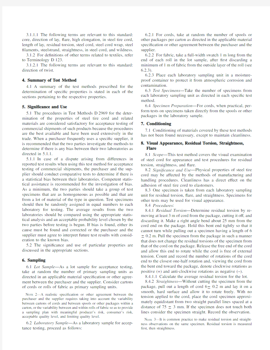
12.4.3Length of Lay —Place a sheet of white paper or carbon paper over a straight-length section of the specimen and rub the paper with a pencil to form a relief impression.Count the number of nodes in the impression for a speci?ed length (not shorter than ?ve times the speci?ed lay length)measured between the center of nodes (see Fig.1).Using the number of strands from 12.4.4,calculate the length of lay of the cord as directed in 12.5.
12.4.4Number of Strands —Separate the outermost compo-nents making up the specimen by unwinding the surface layer.Note and record the number of components in this surface layer.The outermost components may be single ?laments or strands.
12.4.5If the outermost component is comprised of more than one ?lament,unwind a strand from the cord and determine the direction of lay and the length of lay as directed in 12.4.2and https://www.wendangku.net/doc/8c9224837.html,e the number of ?laments determined as directed in 12.4.6and in Eq 6of 12.5to calculate the length of lay of the strands.
12.4.6Number of Filaments —Separate the strand by un-winding and count the number of ?laments in the strand.12.4.7Repeat the procedures in 12.4.2-12.4.6for the core,if present.The core is the innermost component of a construction that remains in the center and does not extend to the surface layer.It can be a single ?lament or a strand.
12.4.8An alternative method for determining the length of lay is the untwisting method,as covered in the section on Twist in Method D 885.A modi?ed twist counter,such as a hand-driven torsion testing machine,is required to untwist the cord due to the stiffness of the cord.Untwist the cord ?rst,then untwist the strands when more than one strand is present.The length of lay is calculated by dividing the initial specimen length as measured between the clamps by the number of turns required to untwist the cord or the strand.For high-elongation cords,apply 0.5mN/tex pretension during the clamping.
12.5Calculation —Calculate the length of lay to the nearest 0.2mm using Eq 6as follows:
8
Supporting data are available from ASTM Headquarters,100Barr Harbor Drive,West Conshohocken,PA 19428.Request RR:
D13-1064.
Length of Lay,mm 5~L /N !3S (6)
where:
L =length over which the number of nodes are counted,
mm,
S =number of strands or ?laments in the surface layer,and N =number of nodes.
12.5.1Calculate the length of lay for the lot.12.6Report :
12.6.1State that the specimens were tested as directed in Section 12of Test Methods D 2969.Describe the material sampled and the method of sampling used.
12.6.2Report the following information for each cord part:12.6.2.1Direction of lay,
12.6.2.2Length of lay for each laboratory sampling unit and for the lot.and
12.6.2.3Number of strands or ?laments,or both.12.7Precision and Bias :
12.7.1Summary —In comparing two averages of four ob-servations the difference between averages should not exceed the following amounts in 95out of 100cases when all of the observations are taken by the same well-trained operator using the same piece of equipment and specimens are randomly drawn from the same sample.
Rubbing Method Cord Lay Length 0.48mm Strand Lay Length 0.20mm Twist Counter Method Cord Lay Length 0.15mm Strand Lay Length
0.08mm
Larger differences are likely to occur under all other circum-stances.
12.7.2Interlaboratory Test Data 7—An interlaboratory test was run in 1983in which randomly drawn specimens of four materials were tested in sixteen laboratories in accordance with Practice D 2904.Ten laboratories used the rubbing method and six laboratories used the twist counter method.Each laboratory used two operators,each of whom tested two specimens of
each material on different days.The components of variance expressed as standard deviations are listed in Table 1(see 9.7.2.1).
12.7.3Precision —For the components of variance reported in Table 1,the averages of two observed values should be considered signi?cantly different at the 95%probability level if the difference equals or exceeds the critical difference listed in Table 2(see Note 5).
12.7.4Bias —The procedures in Test Methods D 2969for determining the cord and strand lay lengths of steel cord have not been checked against accepted reference materials but contain no known bias.These methods are accepted as referee methods (see 9.7.2.1).
13.Thickness of Cord
13.1Scope —A minimum length specimen of strand or cord is held between two parallel circular-faced anvils of a mi-crometer.The movable anvil is closed gradually and gently until it is in contact with the specimen.The thickness is determined by reading the micrometer gage.The out-of-roundness is determined from the minimum and maximum thickness measurements.
N OTE 10—Alternative methods of determining thickness are described in Methods D 885.Optical or non-contact methods for thickness measure-ments,especially of easily deformed cords,are under study.
13.2Signi?cance and Use —Thickness is one of the basic physical properties of strand and cord needed in many indus-trial applications.Tire dimensions and calendered fabric thick-ness are dependent on knowing cord thickness.Production techniques in calendering are also affected by the degree of out-of-roundness of the cord.13.3Apparatus :
13.3.1Precision Micrometer ,with a vernier to provide measurement to the nearest 0.01mm.The anvils shall be plane and parallel within 0.015mm.The dimensions of the anvils should be greater than one lay length.The force on the anvils shall be 1.560.2
N.
Length of lay =(length marked/number of nodes)3the number of ?laments in the strand (see 12.4.6)For the three-?lament strand illustrated,
Length of lay,mm =(75/10)33=22.5mm
FIG.1Diagram Illustrating the Determination of the “Length of
Lay”
13.4Number and Preparation of Specimens:
13.4.1Test one specimen from each laboratory sampling unit.
13.4.2Remove a150-mm specimen from the spool by burning or cutting.The section to be measured may not be bent or kinked.
13.5Procedure:
13.5.1Verify that the measuring instrument reads0.000 when the anvils are closed.
13.5.2Carefully make a right-angle bend in the cord with-out bending or kinking the section to be measured,so as to assist in rotating the cord between measurements and judging the amount of rotation.Determine the maximum and minimum thicknesses at each of three locations approximately100mm apart along the cord.Read and record each measurement to the nearest0.01mm.
13.6Calculations:
13.6.1Calculate the thickness,to the nearest0.01mm,as the average of the three maximum and three minimum mea-surements for each laboratory sampling unit and for the lot.
13.6.2Calculate the difference between each pair of mini-mum and maximum readings for each specimen.The out-of-roundness for the specimen is the maximum difference deter-mined.
13.6.2.1Calculate the average out-of-roundness for the lot.
13.7Report:
13.7.1Report that the specimens were tested as directed in Section13of Test Methods D2969.Describe the material sampled and the method of sampling used.
13.7.2Report the following information:
13.7.2.1Cord thickness for each laboratory sampling unit and for the lot,and
13.7.2.2Out-of-roundness for each laboratory sampling unit and for the lot.
13.8Precision and Bias:
13.8.1Summary—In comparing two averages of four ob-servations,the difference between averages should not exceed the following amounts in95out of100cases when all the observations are taken by the same well-trained operator using the same piece of test equipment and specimens are randomly drawn from the same sample:
Cord Thickness0.01mm
Cord Out-of-Roundness0.02mm
Larger differences are likely to occur under all other circum-stances.The procedures for determining cord thickness and out-of-roundness have no known bias and are considered referee methods.
13.8.2Interlaboratory Test Data7—An interlaboratory test was run in1983in which randomly drawn specimens of four materials were tested in?fteen laboratories in accordance with Practice D2904.Each laboratory used two operators,each of whom tested two specimens of each material on different days. The components of variance expressed as standard deviations are listed in Table1(see9.7.2.1).
13.8.3Precision—For the components of variance reported in Table1,the averages of two observed values should be considered signi?cantly different at the95%probability level if the difference equals or exceeds the critical differences listed in Table2(see Note5).
13.8.4Bias—The procedures in Test Methods D2969for determining thickness and out-of-roundness of steel cord have not been checked against accepted reference materials but contain no known bias.These methods are accepted as referee methods(see9.7.2.1).
14.Brass Coating Analysis by Atomic Absorption(AA) 14.1Scope—The brass coating is stripped from the steel cord using nitric acid,and the composition is determined using ?ame atomic absorption analysis as in Practice E663.The mass of the brass(coating weight)is expressed as the ratio of the total mass of the copper and zinc to the specimen mass prior to stripping.
14.2Signi?cance and Use—The adhesive properties of the cord depend in part on the composition and mass of the brass coating.
14.3Apparatus and Reagents:
14.3.1Atomic Absorption Spectrophotometer—A spectro-photometer capable of being operated in accordance with Practice E663with the following instrument operating param-eters:
Copper Zinc Wavelength324.7nm213.9nm
Fuel/oxidant acetylene/air
Flame oxidizing
Slit width(per operating manual)
14.3.2Calibration Solutions—The following standard solu-tions may be used(fewer may be used based on the operating manual for the speci?c?ame atomic absorption equipment used):
Solution A—1ppm Cu,0.5ppm Zn,5%HNO3(by volume).
Solution B—2ppm Cu,1.0ppm Zn,5%HNO3(by volume).
Solution C—3ppm Cu,1.5ppm Zn,5%HNO3(by volume).
Solution D—4ppm Cu,2.0ppm Zn,5%HNO3(by volume).
Solution E—5ppm Cu,2.5ppm Zn,5%HNO3(by volume).
14.3.3Reference Solution—The reference solution used should be5%(by volume)nitric acid in distilled water. 14.3.4Chloroform,technical grade.
14.3.5Toluene,technical grade.
14.3.6Nitric Acid,reagent grade,69to71%by weight.
14.4Number of Specimens—Take one specimen per subunit in the laboratory sample.
14.5Hazards
14.5.1Refer to the manufacturer’s material safety data sheet (MSDS)for information on handling,use,storage,and dis-posal of chemicals used in this standard.
14.5.2Precaution-In addition to other precautions,safety precautions should be followed when using any of the listed reagents.The reagents should be used only with adequate ventilation(in a hood)and with eye protection.Personnel should be familiar with current emergency?rst aid procedures for each reagent and should obtain medical attention immedi-ately upon accidental contact.
14.5.3Warning-Chloroform acts as a narcotic and anes-thetic at high concentrations,and is toxic by ingestion.
14.5.4Warning-Toluene is a local irritant,may be narcotic in high concentration,and is harmful or fatal if
swallowed.
14.5.5Warning-Nitric acid is corrosive and may cause sever burns of the skin eyes.the vapor is irritating to the mucous membranes.
14.6Procedure:
14.6.1Cut a length of cord to yield a specimen mass between0.2and0.4g without wrap wire.
14.6.2Cut specimens into lengths of approximately30-mm, untwist,and place individual?laments in a suitable test tube.If wrap wire is present,discard and do not include in the analysis. Rinse specimen with a50:50mixture of chloroform and toluene.Drain and dry for30min in a vented oven at100to 105°C.Remove and place in a desiccator and cool to room temperature.
14.6.3Weigh the specimen to the nearest0.1mg and place in a dry200-mL volumetric?ask.Strip coating by covering wires with5mL of nitric acid and magnet stir for30s.Draw and hold the specimen in the neck of the?ask using a magnet, rinse with5mL of nitric acid.While retaining the specimen in the neck of the?ask with a magnet,rinse the specimen several times with distilled water,then carefully remove the specimen using the magnet.
14.6.4Dilute to volume with distilled water and mix. 14.6.5Analyze this solution and applicable calibration so-lutions in accordance with the speci?c?ame atomic absorption spectrophotometer manual and Practice E663.
14.7Calculation:
14.7.1Calculate the copper content to the nearest0.01g of copper/kg of cord,using Eq7:
Copper in brass,%51003ppm Cu/~ppm Cu1ppm Zn!(7) 14.7.1.1Calculate the copper content for the lot.
14.7.2Calculate the zinc content to the nearest0.01g of zinc/kg of cord,using Eq8:
Zinc in brass,%51003ppm Zn/~ppm Cu1ppm Zn!(8) 14.7.2.1Calculate the zinc content for the lot.
14.7.3Calculate the mass of brass(coating weight)to the nearest0.01g/kg using Eq9:
Mass of brass,g/kg50.23~ppm Cu1ppm Zn!/W(9) where:
W=specimen mass,g.
14.7.4Calculate the brass thickness to the nearest10nm, using Eq10:
Thickness,mm50.2343F3mass of brass3100(10) where:
F=diameter of?lament,mm.
14.7.4.1Calculate the brass thickness for the lot.
14.8Report:
14.8.1Report that the specimens were tested as directed in Section14of Test Methods D2969.Describe the material sampled and the method of sampling used.
14.8.2Report the following information:
14.8.2.1Copper content for each laboratory sampling unit and for the lot.
14.8.2.2Zinc content for each laboratory sampling unit and for the lot.
14.8.2.3Mass of brass(coating weight)for each laboratory sampling unit and for the lot.
14.8.2.4Thickness of brass for each laboratory sampling unit and for the lot.
14.9Precision and Bias:
14.9.1Summary—In comparing two averages of four ob-servations,the differences between averages should not exceed the following amounts in95out of100cases when all of the observations are taken by the same well-trained operator using the same piece of test equipment and specimens drawn randomly from the same sample of material:
Mass of brass0.27g/kg
Copper in brass 1.55%
Larger differences are likely to occur under all other circum-stances.The procedures for determining mass of brass and copper in brass have no known bias and are considered referee methods.
14.9.2Interlaboratory Test Data8—An interlaboratory test was run in1981in which randomly drawn specimens of nine materials were tested in twenty-two laboratories in accordance with Practice D2904.Each laboratory used two operators, each of whom tested two specimens of each material.In analyzing the data,the results from two laboratories were discarded because there was evidence that the procedure was improperly applied in those two laboratories due to inexperi-enced operators.The components of variance,expressed as standard deviations,are listed in Table1.
14.9.2.1The materials used in both the1981and the1983 interlaboratory tests for brass analysis were(134)+(634) 30.175+130.15construction with the nominal properties of:
Copper Percentages in Coating—63,67.5,72
Mass of Brass(g/kg)—3.66,5.12,6.59in all possible combi-
nations
14.9.3Precision—For the components of variance reported in Table1,two averages should be considered signi?cantly different at the95%probability level if the difference equals or exceeds the critical differences listed in Table2(see Note5).
14.9.4Bias—The procedures in Test Methods D2969for determining mass of brass and copper in brass on?laments, strands,cords,and fabric made from steel cords have not been checked against accepted reference materials but contain no known bias.These procedures are accepted as referee methods.
15.Brass Coating Analysis by X-Ray Emission or
Fluorescence Spectroscopy(XRF)
15.1Scope—Steel cord specimens38mm long are placed side by side on a holder and irradiated with X-rays.The resultant emissions are used to calculate the mass of brass and the copper content in the brass.
15.2Signi?cance and Use—The adhesion properties of steel cord depend in part on the mass of brass and the brass composition.
15.3Apparatus:
15.3.1X-ray Spectrometer,with?ne slit(see Note
11).
15.3.2Calibration Standards—Brass standards from the National Institute for Standards and Technology(NIST)9 should be used to con?rm proper apparatus operation based on procedures speci?ed for the particular spectrometer being used. Recommended standards taken and the percent copper in brass is calculated to the nearest0.01%using Eq11:
Cu,%5~CuK a Intensity3100!/~CuK a1ZnK a Intensities!
(11) where:
CuK a=number of intensity counts at the CuK a wave-length,and
ZnK a=number of intensity counts at the ZnK a wave-length.
This value must fall within60.5%of the nominal copper value for the NBS standard.
N OTE11—Precaution:In addition to other precautions,observe occu-pational health and safety standards10on ionizing radiation at all X-ray emission spectrometer installations.X-ray equipment should be used only under the guidance and supervision of a responsible,quali?ed person.
15.3.3Suitable monitoring devices,either?lm badges or dosimeters,shall be worn by all personnel using the equipment. Periodic radiation surveys of the equipment for leaks and excessive scattered radiation shall be made by a quali?ed person using an ionization chamber detector in accordance with local,state,and national radiation standards.The personal ?lm badge survey record,the radiation survey record,and a maintenance record shall be available upon request.
15.3.4Special precautions for the operator shall be posted.
15.3.5X-ray caution signs shall be posted near the X-ray equipment and at all entrances to the radiation area.
15.3.6Fail-safe“X-Ray On”warning lights shall be used in the immediate area of the equipment.
15.4Number of Specimens—Unless otherwise agreed upon, take one specimen per subunit in the laboratory sample. 15.5Procedure:
15.5.1Calibration Curves—Due to the effect of specimen geometry,separate calibration curves must be established for each steel cord construction to be analyzed.The brass compo-sition and mass of brass of the specimens used to establish the calibration curves must encompass the expected values of the material to be analyzed.Equipment operating conditions dur-ing establishment of calibration curves must be the same as those to be utilized during subsequent analysis.
15.5.1.1Using a series of specimens drawn from samples whose brass composition and mass of brass have been previ-ously determined in accordance with Section14,the copper to brass ratio and the brass to iron ratio as de?ned by Eq12and Eq13are plotted versus the previously determined copper content and mass of brass values for those same samples.
R15~CuK a intensity!/~CuK a intensity1ZnK a intensity!(12)
R25~CuK a intensity1ZnK a intensity!/~FeK b intensity!(13) where:
FeK b=number of intensity counts at the FeK b wave-length,
R1=ratio to be plotted versus the known percentage copper,and
R2=ratio to be plotted versus the known mass of brass.
Data collection must be in accordance with the recom-mended operating procedure of the spectrometer.Analyze duplicate specimens.If results are not within0.4%for copper and0.1g/kg for mass of brass,analyze a third specimen. 15.5.2Cut40specimens each38mm long.Place specimens side by side in a coplanar con?guration and tape both ends. These are now ready for analysis in accordance with the operating procedures for the spectrometer.
15.5.3Analyze the specimens in accordance with the oper-ating procedures for the spectrometer.Record intensity values for CuK a,ZnK a,and FeK b.
15.6Calculations:
15.6.1Compute ratios as directed in14.7and determine the percent copper and mass of brass from the calibration curves established in accordance with14.7.
15.6.2Determine zinc content by subtracting percent cop-per from100%.
15.6.3Calculate the brass coating thickness to the nearest 10nm using Eq14:
Thickness,mm50.2343F3mass of brass31000(14) where:
F=diameter of?lament,mm.
15.7Report:
15.7.1Report that the specimens were tested as directed in Section15of Test Methods D2969.Describe the material sampled and the method of sampling used.
15.7.2Report the following information:
15.7.2.1Mass of brass(coating weight)for each laboratory sampling unit and for the lot.
15.7.2.2Copper content for each laboratory sampling unit and for the lot.
15.7.2.3Zinc content for each laboratory sampling unit and for the lot.
15.7.2.4Thickness of brass for each laboratory sampling unit and for the lot.
15.8Precision and Bias:
15.8.1Summary—In comparing two averages of four ob-servations the difference between averages should not exceed the following amounts in95out of100cases when all of the observations are taken by the same well-trained operator using the same piece of test equipment and specimens drawn from the same sample:
Mass of brass0.14g/kg
Copper in brass0.43%
Larger differences are likely to occur under all other circum-stances.The procedures for determining mass of brass and copper in brass as directed in Section15have no known bias.
9Calibration standards may be obtained through the National Institute for Standards and Technology,U.S.Department of Commerce,Washington,DC20234.
10Federal Register,V ol36,No.105.May29,1971,Sec1910.96or of latest issue of Subpart G;Superintendent of Documents,https://www.wendangku.net/doc/8c9224837.html,ernment Printing Office, Washington,DC20025;National Bureau of Standards Handbook111,ANSI
N43.2-1971.
15.8.2Interlaboratory Test Data11—An interlaboratory test was run in1983in which randomly drawn samples of nine materials were tested in six laboratories in accordance with Practice D2904.Each laboratory used two operators,each of whom tested two specimens of each material on different days. The components of variance expressed as standard deviations are listed in Table1.The samples used in this interlaboratory test were drawn from the same group of samples used in the interlaboratory test discussed in14.9.2(see14.9.2.1).
15.8.3Precision—For the components of variance reported in Table1,the averages of two observed values should be considered signi?cantly different at the95%probability level if the difference equals or exceeds the critical differences listed in Table2(see Note5).
15.8.4Bias—The procedures in Section15,Test Methods D2969,for determining the mass of brass and the copper in brass on?laments,strands,cords,and fabrics made from steel have not been checked against accepted reference materials but contain no known bias.The procedure in Section15is not an accepted referee method.
16.Static Adhesion of Filaments,Strands,and Cords to
Elastomers
16.1Determine the adhesion of strands and cords to elas-tomers as directed in Test Method D2229.
16.2Determine the adhesion of?laments to elastomers as directed in Test Methods D1871.
16.3Determine the peel adhesion of cords or?laments as directed in Test Method D4393.
17.Keywords
17.1adhesion;brass coating;direction of lay;elongation; linear density;steel cord;strength,breaking;thickness;visual appearance
ANNEX
(Mandatory Information)
A1.NOMENCLATURE SYSTEM FOR STEEL CORDS
A1.1Format:
(S3F)3D+(S3F)3D+(S3F)3D+F3D
A1.2Sections—The sections of the format are listed in order of sequence of manufacture of the cord structure: (innermost)(intermediate)(outermost)(wrap)
A1.3Components:
S=number of strands,
F=number of?laments,and
D=nominal diameter of?laments,0.001mm.
A1.4General Rules:
A1.4.1Start with the innermost part and proceed outward. A1.4.2Separate each part by a plus(+)sign.
A1.4.3Parentheses are used for clarity to differentiate a part that consists of more than one component.Filaments and strands enclosed in parentheses form a part,the center of which is not the center of the cord.
A1.4.4When S or F=1,omit S or F in the format A1.1to obtain short form of nomenclature.
A1.4.5If the diameter is the same for two or more parts, omit the diameter except for the last part before the change.The?lament diameter of the last part before the spiral wrap and the?lament diameter of the spiral wrap should always be written out.
A1.4.6The lay and direction of lay may also be indicated with the construction as in the following example:
(133)+(634)30.20+130.15construction 10/10/14/ 3.5/
S/S/Z/S/
core/outer/cord/spiral wrap
strand
More commonly identi?ed as73430.20+130.15.
A1.5Special Constructions—There may be special cord constructions that are nonsymmetric or that contain nonheli-coidal elements and cannot be adequately described under this nomenclature system.In these instances a clear understanding must be established between the producer and user as to the geometry of each such cord construction.
N OTE A1.1—It is difficult to measure the diameter of the?lament with a micrometer after it has been combined with other?laments to form a strand or cord due to undulations in the wire.The diameter of the?lament may be measured using optical instruments or blade anvils in a microme-ter.For identi?cation of?laments in the nomenclature system,the nominal diameter of the?laments before forming as given by the supplier is used. N OTE A1.2—The nomenclature system describes the steel cord con-struction as manufactured by the producer.Various abbreviated methods have been derived from this system.All of these can be expressed in the above format.
11Supporting data are available from ASTM Headquarters.Request RR:D13-
1071.
APPENDIX
(Nonmandatory Information)
X1.SUGGESTED DATA FORM FOR REPORTING TEST RESULTS
X1.1To facilitate the reporting of test results for a lot of steel tire cord,especially when the data is to be transmitted electronically or recorded on tapes or diskettes designed to be read electronically,the data form in Table X1.1is recom-mended.
X1.2The key element in the suggested form is that neither the characteristic nor the lot identi?cation associated with each line sequence number be violated.As an example,if data on linear density is required,then it must be preceded by the line sequence number 10.If data on a certain characteristic is not required,then no adjustment should be made in the line sequence numbers for the subsequent characteristics;simply do not utilize the line sequence number shown for the character-
istic for which no data is required.
X1.3It is suggested that line sequence numbers of 30or greater be used for characteristics that are not the subject of an ASTM standard.This procedure will facilitate the possible future expansion of ASTM standards.
X1.4Addition,deletion,or reordering of columns within the form should be only by mutual agreement between the purchaser and the supplier.
X1.5Restrictions on the values of entries within a row,between rows,and between groups of rows should be by mutual agreement between the purchaser and the supplier.
TABLE X1.1Data Form for Test Results from Lots of Steel Tire Cord A
Line
Sequence No.
Lot Identi?cation
01Supplier code:NNN Supplier category:N 02Purchaser speci?cation number:8AAAAAAAAAAAAAAA’
Purchaser plant code:NN 03Date shipped:8YYMMDD’Purchase order No:8AAAAAAAAAA’Date tested:8YYMMDD’
04Steelcord construction:8AAAAA’Supplier lot No:8AAAAAAAA’Brass analysis method:8AAA’
05Type spool:8AAAAAAA’
Number of spools:NNNN Characteristic
Samples Average Standard Deviation Minimum Maximum CPK Limit 06Cord thickness NN N.NNN N.NNN N.NNN N.NNN NN.NN 8A’07Breaking force:NN NNNNN.NNNN.N NNNNN.NNNNN.NN.NN 8A’08Adhesion force:NN NNNN.NNNN.N NNNN.NNNN.NN.NN 8A’09Adhesion coverage:NN NNN.N NN.N NNN NNN NN.NN 8A’10Linear density NN NNNNN.NNNN.N NNNNN.NNNNN.NN.NN 8A’11Percent copper:NN NN.N NN.N NN.N NN.N NN.NN 8A’12Plating mass:NN N.NN N.NN N.NN N.NN NN.NN 8A’13Residual torsions:NNNN NN.NN NN.NN NN.NN NN.NN NN.NN 8A’14
Elongation at break:
NN
NN.NN
NN.NN
NN.NN
NN.NN
NN.NN
8A’
Residual Torsions:
3.0
15Histogram:
NNNN NNNN NNNN NNNN NNNN NNNN NNNN NNNN NNNN NNNN NNNN NNNN NNNN NNNN NNNN
16Flare:8AA’Straightness:
8AA’
30Low load elongation:NN NN.NN NN.NN NN.NN NN.NN NN.NN 8A’31Elasticity:NN NN.N NN.N NN NN NN.NN 8A’32Spare N N N N N N —33Spare N N N N N N —34
Spare
N
N
N
N
N
N
—
Symbol Dictionary:
A –alphanumeric character N —numeric character
YYMMDD —international date format
A
All test methods and reporting units must be in accordance with purchaser
speci?cation.
ASTM International takes no position respecting the validity of any patent rights asserted in connection with any item mentioned in this https://www.wendangku.net/doc/8c9224837.html,ers of this standard are expressly advised that determination of the validity of any such patent rights,and the risk of infringement of such rights,are entirely their own responsibility.
This standard is subject to revision at any time by the responsible technical committee and must be reviewed every?ve years and if not revised,either reapproved or withdrawn.Your comments are invited either for revision of this standard or for additional standards and should be addressed to ASTM International Headquarters.Your comments will receive careful consideration at a meeting of the responsible technical committee,which you may attend.If you feel that your comments have not received a fair hearing you should make your views known to the ASTM Committee on Standards,at the address shown below.
This standard is copyrighted by ASTM International,100Barr Harbor Drive,PO Box C700,West Conshohocken,PA19428-2959, United States.Individual reprints(single or multiple copies)of this standard may be obtained by contacting ASTM at the above address or at610-832-9585(phone),610-832-9555(fax),or service@https://www.wendangku.net/doc/8c9224837.html,(e-mail);or through the ASTM website (https://www.wendangku.net/doc/8c9224837.html,).
六年级下册数学教案-三解决问题的策略选择策略解决问题苏教版
选择策略解决问题 教学内容:教材例1,练一练,练习五第1~3题。 教学目标:1.通过练习让学生熟练运用转化和假设的策略来解决问题。 2.在不断练习和反思中,感受运用策略对于解决特定问题的价值。 3.通过这些策略的运用,了解解题方法的多样性,感受数学知识的魅力。 教学重点:学会假设和调整的策略来解决问题,并体会假设与调整的多样性。教学难点:掌握用转化的策略解决分数问题的方法。 教学过程: 一.回顾旧知,整理策略 出示:甲是乙的5/6,丙是乙的1/6,丙是甲的()。 师:这里用了3个分数来表示甲、乙、丙三者之间的关系。你能用一个简单的方式把这三者之间的关系直接地表示出来吗?(画图,连比) 师:同学们在表示三者关系的过程中用到了哪些常用的策略?(画图和转化)谈话:同学们从不同的角度用了不用的策略来理解并表示甲、乙、丙的关系。从三年级上册起,每一册数学都教学一种策略,你们知道我们学了哪些策略?(学生可能已经忘记,教师帮助回顾整理:依次是分析量关系的“从条件向问题推理”和“从问题向条件推理”,帮助理解题意的“列表整理”和“画图整理”,还有“枚举”“转化”“假设与替换”等策略) 提问:这些策略你们都学会了吗?今天我们将合理的选择这些策略来解决新的问题,大家愿意接受挑战吗?(板书课题:转化的策略) 二.合作探究,运用策略 1、教学例1(课件出示例1) 学生读题 谈话:这是一个稍复杂的分数问题,根据男生人数占总人数的2/5,你能想到什么?(引导学生进一步分析) 小组交流方法。 汇报交流情况:(学生遇到困难可作适当的引导。) ①根据“男生人数是女生的2/3”理解2/3这 个分数的意义,可以画线段图,看出男生人数是美 术组总人数的2/5。原来的问题就转化成美术组一 共有35人,男生人数是总人数的2/5,女生人数 是总人数的3/5,男生有多少人?女生有多少人? 这是简单的求一个数的几分之几是多少的问题。 ②根据分数2/3的意义,可以推理出“男生人数和女生人数的比是2∶3”。原来问题就转化成美术组一共有3/5人,男生与女生人数的比是2∶3,男生、
反应器介绍(操作方式、操作条件)5页
反应器介绍 简介 用于实现液相单相反应过程和液液、气液、液固、气液固等多相反应过程。器内常设有搅拌(机械搅拌、气流搅拌等)装置。在高径比较大时,可用多层搅拌桨叶。在反应过程中物料需加热或冷却时,可在反应器壁处设置夹套,或在器内设置换热面,也可通过外循环进行换热。 反应器的应用始于古代,制造陶器的窑炉就是一种原始的反应器。近代工业中的反应器形式多样,例如:冶金工业中的高炉和转炉;生物工程中的发酵罐以及各种燃烧器,都是不同形式的反应器。 类型 常用反应器的类型(见表)有:①管式反应器。由长径比较大的空管或填充管构成,可用于实现气相反应和液相反应。②釜式反应器。由长径比较小的圆筒形容器构成,常装有机械搅拌或气流搅拌装置,可用于液相单相反应过程和液液相、气液相、气液固相等多相反应过程。用于气液相反应过程的称为鼓泡搅拌釜(见鼓泡反应器);用于气液固相反应过程的称为搅拌釜式浆态反应器。③有固体颗粒床层的反应器。气体或(和)液体通过固定的或运动的固体颗粒床层以实现多相反应过程,包括固定床反应器、流化床反应器、移动床反应器、涓流床反应器等。④塔式反应器。用于实现气液相或液液相反应过程的塔式设备,包括填充塔、板式塔、鼓泡塔等(见彩图)。⑤喷射反应器。利用喷射器进行混合,实现气相或液相单相反应过程和气液相、液液相等多相反应过程的设备。⑥其他多种非典型反应器。如回转窑、曝气池等。
操作方式 反应器按操作方式可分为: ①间歇釜式反应器,或称间歇釜。 操作灵活,易于适应不同操作条件和产品品种,适用于小批量、多品种、反应时间较长的产品生产。间歇釜的缺点是:需有装料和卸料等辅助操作,产品质量也不易稳定。但有些反应过程,如一些发酵反应和聚合反应,实现连续生产尚有困难,至今还采用间歇釜。 间歇操作反应器系将原料按一定配比一次加入反应器,待反应达到一定要求后,一次卸出物料。连续操作反应器系连续加入原料,连续排出反应产物。当操作达到定态时,反应器内任何位置上物料的组成、温度等状态参数不随时间而变化。半连续操作反应器也称为半间歇操作反应器,介于上述两者之间,通常是将一种反应物一次加入,然后连续加入另一种反应物。反应达到一定要求后,停止操作并卸出物料。 间歇反应器的优点是设备简单,同一设备可用于生产多种产品,尤其适合于医药、染料等工业部门小批量、多品种的生产。另外,间歇反应器中不存在物料的返混,对大多数反应有利。缺点是需要装卸料、清洗等辅助工序,产品质量不易稳定。 ②连续釜式反应器,或称连续釜,可避免间歇釜的缺点,但搅拌作用会造成釜内流体的返混。在搅拌剧烈、液体 粘度较低或平均停留时间较长的场合,釜内物料流型可视作全混流,反应釜相应地称作全混釜。在要求转化率高或有串联副反应的场合,釜式反应器中的返混现象是不利因素。此时可采用多釜串联反应器,以减
办公软件试题操作要求及题解步骤
办公软件应用(Windows平台)(高级操作员级) 试题及题解步骤 王 毅 2006.6 主要内容 1 操作系统应用 2 文档处理的基本操作 3 文档处理的综合操作 4 数据表格处理的基本操作 5 数据表格处理的综合操作 6 演示文稿的制作 7 办公软件的联合应用 8 桌面信息管理程序应用 9 其他高级应用 第一单元 操作系统应用 操作要求:考生按如下要求进行操作。 1. 开机,进入windows,启动“资源管理器”。 2. 建立考生文件夹,文件夹名为考生准考证后七位。 3. C盘中有考试题库“win2004gjw”文件夹,文件夹结构如图: 4. 根据选题单指定题号,将题库中ksml2文件夹内相应的文件复制 到考生文件夹中,将文件分别重命名为A1、A2 、A3 、A4 、 A5 、 A6 、 A7 、 A8,扩展名不变。 5. 系统设置与优化: 1) 用磁盘清理程序对C驱动器进行清理,在进行磁盘清理时将整 个屏幕以图片的形式保存到考和文件夹中,文件命名为A1a。 (不必等待操作执行完毕) 2) 自定义任务栏,设置任务栏中的时钟隐蔽,并且在“开始”菜单 中显示小图标,将设置的效果屏幕以图片的形式保存到考生文 件夹中,文件命名为A1b,图片保存之后,恢复原设置。 解题步骤:
1. 右击“我的电脑”图标→资源管理器。 2. 在资源管理器中单击D:盘→右击右侧空白区域→新建→文件夹 →输入文件夹名(准考证号后七位数字)→回车确定。 3. 根据选题单→把相应文件选定(按Ctrl单击每个文件)→右键菜 单→复制;打开考生文件夹→右键菜单→粘贴→全选→右键菜单 →属性→取消只读→右击文件→重命名→输入相应文件名。 4. 系统设置与优化,并以图片形式保存。方法:按PrtSc/SysRq 键,保存整个桌面,按Alt+P键保存当前活动窗口。或用红蜻蜓 抓图精灵。 a) 开始→附件→系统工具→磁盘清理程序→磁盘碎片整理程序→ 按PrtSc键→启动画图程序→粘贴→保存在考生文件夹下,文件名为A1a。 b) 右击任务栏→属性→在对话框中按要求设置→勾选隐藏时钟→ 开始菜单标签→自定义→勾选显示小图标→确定。 第二单元 文档处理的基本操作 操作要求:打开文档A2.doc,按照样文进行如下操作: 1. 设置文档的页面格式: a) 按样文2-1A,设置页眉和页脚,在页眉左侧录入文本“音乐的 魅力”,右侧插入域“第X页共Y页”。 b) 按样文2-1A,将正文前两段设置为三栏格式,加分隔线。 2. 设置文档的编排格式: a) 按样文2-1A,将标题设置为艺术字,式样为艺术字库的第2行 第5列,字体为华文行楷,环绕方式为紧密型。 b) 按样文2-1A,将正文前两段字体设置为楷体、小四,字体颜色 为蓝色。 c) 按样文2-1A,将正文最后一段设置为仿宋,小四。 d) 按样文2-1A,将正文第一段设置为首字下沉格式,下沉行数为 二行,首字字体设置为华文行楷。 3. 文档的插入设置: a) 在样文所示位置插入图片,图片为ksml3\tu2-1.bmp,设置图片 大小缩放28%,环绕方式为紧密型。 b) 在最后一段“奋进”文本处添加批注“此处用词不当。” 4. 插入、绘制文档表格:在文档尾部插入一一个3行3列的表格并 合并第3列单元格。 5. 文档的整理、修改和保护:保护的窗体,密码为ks2-1。
操作系统复习题与答案
《操作系统》练习及参考答案 第1章操作系统概述 1.3.1 选择最合适的答案 1.一般用户更喜欢使用的系统是()。 A.手工操作 B.单道批处理 C.多道批处理 D.多用户分时系统 2. 与计算机硬件关系最密切的软件是()。 A.编译程序 B.数据库管理系统 C.游戏程序 D.OS 3. 现代OS具有并发性和共享性,是()的引入导致的。 A.单道程序 B. 磁盘 C. 对象 D.多道程序 4. 早期的OS主要追求的是()。 A.系统的效率 B.用户的方便性 C.可移植 D.可扩充性 5.()不是多道程序系统 A.单用户单任务 B.多道批处理系统 C.单用户多任务 D.多用户分时系统 6.()是多道操作系统不可缺少的硬件支持。 A.打印机 B.中断机构 C.软盘 D.鼠标 7. 特权指令可以在()执行。 A.目态 B.浏览器中 C.任意的时间 D.进程调度中 8. 没有了()计算机系统就启动不起来。 A.编译器 B.DBMS C.OS D.浏览器 9. 通道能够完成()之间的数据传输。 A.CPU与外设 B.存与外设 C.CPU与主存 D.外设与外设 10. 操作系统的主要功能有()。 A.进程管理、存储器管理、设备管理、处理机管理 B.虚拟存储管理、处理机管理、进程调度、文件系统 C.处理机管理、存储器管理、设备管理、文件系统 D.进程管理、中断管理、设备管理、文件系统 11. 单处理机计算机系统中,()是并行操作的。 A.处理机的操作与通道的操作是并行的 B.程序与程序 C.主程序与子程序 D.用户程序与操作系统程序 12. 处理机的所有指令可以在()执行。 A.目态 B.浏览器中 C.任意的时间 D.系统态 13.()功能不是操作系统直接完成的功能。 A.管理计算机硬盘 B.对程序进行编译 C.实现虚拟存储器 D.删除文件
第十三回不确定性条件下的选择
第十三回不确定性条件下的选择 之一:期望效用函数理论13.0 温故而知新: 1.数学期望 2.方差 13.1 你选择哪个方案? A.投硬币碰运气,正面给你100,反面啥也没有; B.直接给你50元? C.直接给你40元? …… 在上面的事情里,我们有以下概念: 1.期望效用 2.风险的主观态度 3.确定性等值 4.保险金 13.2 期望效用函数 1.如果某个随机变量X以概率P i取值x i,i=1,2,…,n,而某人在确定地得到x i时的效用为u(x i),那么,该随机变量给他的效用便是: U(X)=E[u(X)]=P1u(x1)+ P2u(x2)+ …+P n u (x n) 其中,E[u(X)]表示关于随机变量X的期望效用。因此U(X)称为期望效用函数,又叫做冯·诺依曼—摩根斯坦效用函数(VNM函数)。 2.一个例子:李四的财富效用函数为u(x)=x。有人向他兜售彩票,该彩票有50%的可能性中奖4元,问该彩票对他的效用是多少? 3.又一个例子:张三总共有100元钱,他要参加第二天早上的微观经济学考试。按照经验,他有10%的可能性会睡过头,如果这样他会错过考试,则需要交100元以参加重修。他对财富的效用函数为u(x)=x,问他的期望效用函数是多少? 4.期望效用函数是否具有序数性? u和v是两个不同的序数效用函数,若 u(A)=60,u(B)=20, u(C)=0 v(A)=60,v(B)=40, v(C)=0
上面都可以得到A优于B,B优于C的结论;而且u 可以通过某种单调变换得到v 。所以u 和v 代表相同的偏好顺序。但考虑下面: 让消费者选择:一是确定地得到B;另一个是赌局,即掷硬币来得到A或C。分别用u 和v 来分析,结论如何? ——结论:期望效用函数失去了保序性。 13.3 风险的主观态度 1. 风险厌恶 4. 期望效用模型靠得住吗?—— Kahneman 和Tversky 的实验 13.4 确定性等值 1. 若某人的财富效用函数为u(x),而一个赌局对某人的效用为u(E(x)),则有一个CE 值能够满足:u(CE)=u(E(x))。称CE 为某人在该赌局中的确定性等值。 2.前面介绍了李四和张三的故事,他们的确定性等值各是多少?对于他们来说,确定性等值各有什么经济含义? 13.5 风险问题的解决——保险 1.保险市场的价格——保险金:若某人的财富数量为w ,其财富效用函数为u(x),而一个赌局对某人的效用为u(E(x)),若有u(w-R)= u(E(x)),则称R 为保险金。 图13.1 风险厌恶 图13.2 风险偏好 u(E(x))>E(u(x)) 风险厌恶的效用函数是凹函数。 如图13.1所示。 2. 风险偏好 u(E(x)) 二、选择题 1.以下有关操作系统的叙述中,哪一个是不正确的? (1) 1.操作系统管理系统中的各种资源 1.操作系统为用户提供的良好的界面 1.操作系统就是资源的管理者和仲裁者 1.操作系统是计算机系统中的一个应用软件 2.操作系统所占用的系统资源和所需的处理器时间称为 (1) 1.资源利用率 1.系统性能 1.系统吞吐率 1.系统开销 3.操作系统所管理的资源包括:Ⅰ1PU Ⅱ程序Ⅲ数据Ⅳ外部设备 (1) 1.Ⅰ和Ⅱ 1.Ⅱ和Ⅲ 1 Ⅰ、Ⅱ和Ⅲ 1.全部 4.分时操作系统的主要特点是 (1) 1.个人独占机器资源 1.自动控制作业运行 1.高可靠性和安全性 1.多个用户共享主机资源 5.分时操作系统的主要目标是 (1) 1.提高计算机系统的实时性 1.提高计算机系统的利用率1.提高软件的运行速度 1.提高计算机系统的交互性 7.完成中断响应工作的是 (1) 1.系统核心 1.中断处理程序 1.用户程序 1.中断硬件装置 8.如果有多个中断同时发生,系统将根据中断优先级响应优先级高的中断请求,若要调整中断事件的响应次序,可以利用 (1) 1.中断嵌套 1.中断响应 1.中断屏蔽 1.中断向量 9.以下有关强迫性中断事件的叙述中,哪一个是错误的 (1?) 1.输入输出中断来自通道或各种外部设备,用于反映通道或设备的工作情况 1.程序性中断,是正在运行程序有意识安排的而引起的中断 1.硬件故障中断是机器发生错误时产生的中断 1.时钟中断是硬件时钟到时等 10.下列中断中,哪一个不属于强迫性中断 (1) 1.设备出错 1.掉电 1.时间片到时 1.执行print语句 11.下列哪一个中断属于程序性中断 (1) 1.打印机结束工作 1.地址越界 1.时间片到时 1.掉电 12.在中断处理中,输入输出中断是指 (1) Ⅰ.设备出错Ⅱ.数据传输结束 1.只有Ⅰ 1.只有Ⅱ 1.Ⅰ和Ⅱ 1.都不是 14.计算机系统中设置的访管指令 (1) 1.只能在目录下执行 1.只能在管态下执行 第五章不确定条件下的选择 前面两章讨论了确定性环境中的消费选择问题,即涉及的价格、收入、消费量等变量都具有确定性。然而实际消费选择并非总是在这种确定性环境中进行的,比如人们可以借款进行超支消费,如借款购房或贷款进大学接受高等教育,这种超支消费同人们未来收入有关,然而未来是不确定的,一个人的未来收入可能提高,也可能降低,也可能失业而只能享受社会救济。如果未来收益很低,那么当前的超支在未来就无能力偿付。因此,当前是否要超支消费,这是一个不确定的消费选择问题。又如择业,是在国有企事业单位找一份工作,以求得稳定的(较低)工资收入和安全的社会保障,还是在合资企业求得一个高薪职位但面临很大风险呢?一个人是把他(她)的余款存入银行以求得安全的低利息收入,还是利用余款购买股票进行投资,求得一个高收益但面临较大风险呢?这还是一个带不确定性的选择问题。本章讨论这种不确定条件下的消费选择问题。 第一节不确定性选择事例 通常的“不确定”一词,是说人们不能确定某种行为一定会发生某种结果。经济学家对这个词的含义进行了严格界定,区分了两个不相同但相联系的概念:不肯定性与风险。 不肯定性(uncertainty)是指人们既不能确定某种经济行为一定会发生某种结果,又不能确定其发生的可能性大小。出现不肯定性的原因可能是人们行为本身就具有不确定性因素,或者是人们行为不完全独立,或者是人们缺乏必要的信息等等。 风险(risk)是指人们虽然不能确定某种经济行为一定会发生某种结果,但能够确定其发生的可能性大小,或者说,经济行为产生某种结果的可能性大小是客观存在,由客观条件决定。比如人们可以根据已有的经验,确定出某种经济行为的各种可能结果,并且确定出每种结果发生的概率。这样一来,便可计算这种经济行为的期望值,并利用期望值进行分析。 下面来看不确定性条件下选择的几个事例。 例1. 抽彩(lottery) 设有两种奖品通过抽彩才能获得。第一种抽彩方式(即第一种彩票)是:获得奖品1的概率为p ,获得奖品2的概率为p -1。第二种抽彩方式(即第二种彩票)是:获得奖品1的概率为q ,获得奖品2的概率为q -1。抽彩人得到奖品1后,能获得1U 个单位的效用;获得奖品2后,能获得2U 个单位的效用。问抽彩人喜欢抽哪一种彩票? 要回答这个问题,需要计算这两种彩票的预期效用(即效用的期望值)。用1EU 表示第一种彩票的预期效用,2EU 表示第二种彩票的预期效用。根据概率论的有关知识可知, 211)1(U p pU EU -+= , 212)1(U q qU EU -+= 比较一下1EU 和2EU 的大小,如果21EU EU >,说明第一种彩票的效用期望值更大,因此抽彩人更喜欢第一种抽彩方式,选择第一种彩票。同理,当21EU EU <时,抽彩人会选择第二种彩票。当21EU EU =时,两种彩票的效用期望相同,因而对抽彩人来说无差异。 这个例子同时也说明,一种彩票可以用抽彩的中奖概率分布来表示。比如说有一种彩票有n 个等级的奖励:1等奖,2等奖,…,1-n 等奖(末等奖),n 等奖(无奖)。获得i 等奖的 操作系统的设计目标:方便性;有效性;可扩充性;开放性。 方便性和有效性是操作系统的设计中最重要的两个目标。 1990年后开放性已成为新系统或软件能否被广泛应用的至关重要管的两个目标。操作系统的基本特征:并发性;共享性;虚拟性;异步性。 并发性和共享性是多用户,多任务操作系统两个最基本的特征。 并发性是多用户,多任务操作系统最重要的特征。 在OS基本特征中,异步性是指进程是以人们不可预知的速度向前推进的。 操作系统基本类型:批处理系统;分时系统;实时系统; 在操作系统基本类型中,可靠性是实时系统最重要的特征。 操作系统主要功能:处理机管理;存储器管理;设备管理;文件管理;用户接口;操作系统的用户接口:命令接口;程序接口;图形用户接口; 在操作系统接口中,程序接口亦称为系统调用; 目前比较流行的操作系统(实例)Windows;UNIX;Linux; UNIX系统最本质的特征(英文缩写):OSI UNIX系统的内核结构可分为两大部分:进程控制子系统;文件子系统; 进程三种基本状态:就绪状态;执行状态;阻塞状态; 进程所请求的一次I/O完成后,将是进程状态从阻塞状态变为就绪状态。 操作系统中处于执行状态的进程时间用完后进程状态将转变为就绪状态。 操作系统处于执行状态的进程提出I/O请求后,进程状态将转变为阻塞状态; 进程三种基本状态中,就绪状态是指进程已分配到除CPU以外所有必要资源。 进程同步机制应遵循的准则:空闲让步;忙则等待;有限等待;让权等待; 同步机制准则中,让权等待是指当进程不能自己进入自己的临界区时,应立即释放处理机; 进程,文件,线程在系统中存在的唯一标志(英文缩写):PCB;FCB;TCB; 在系统流利用数据结构(英文缩写)PCB描述进程的基本情况和活动过程; 系统将被中断的CPU现场信息保护在该进程的数据结构(英文缩写)PCB中; 在操作系统中,实现进程的同步的机制:信号量机制;管程机制; 1965年,荷兰学者Dijkstra提出的信号量机制是一种卓越有效的进程同步工具;产生进程死锁的必要条件:互斥条件;请求和保持条件;不剥夺条件;环路等待条件。 在死锁的条件中,不剥夺条件是指进程已获得的资源只能在使用完时由自己释放。在死锁的条件中,互斥条件是指在一段时间内,某资源只能被一进程占用。 资源的按序分配法是摒弃死锁条件中的环路等待条件来预防死锁的发生。 现代操作系统产生死锁的条件中,互斥条件是不能被摒弃来预防死锁的发生。 抢占式进程调度方式基于的主要原则:优先权原则;短进程优先原则;时间片原则。 通常采用解除死锁的两种方法:剥夺资源;撤销进程; 产生进程死锁的原因可归结为两点:竞争资源;进程间推进顺序非法; 1928年,Peter J.Denning指出程序执行时显现出:时间局限性,空间局限性 虚拟存储器的理论依据:局部性原理 在局部性原理中,产生时间局限性的典型原因是在程序中存在着大量的循环操作在局部性原理中,产生空间局限性的典型情况是程序的循序执行 请求分页系统的主要硬件支持:请求页表机制,缺页中断机构,地址变换机构 在请求分页系统的硬件支持中,当所要访问的页面不在内存时,由缺页中断机制 1、Access字段名长度最多为____个字符。 答案: 1:64 2、Access中,文本框分为3种类型:结合型、非结合型与____。 答案: 1:计算型 3、OpenForm操作打开____。 答案: 1:窗体 4、操作查询共有4种类型,分别是删除查询、生成表查询、____和更新查询. 答案: 1:追加查询 8、在Access中数据类型主要包括:自动编号、文本、备注、数字、货币、日期/时间、是/否、OLE对象、____和查阅向导等。 答案: 1:超链接 9、纵栏式窗体将窗体中的一个显示记录按____分隔。 答案: 1:列 10、Access2007中,对数据库表的记录进行排序时,数据类型为____、超级链接或OLE对象的字段不能排序 答案: 1:备注型 11、链接是直接将____中的数据使用到Access的表、窗体、查询和报表中。一旦外部数据源发生变化,则所链接的表、查询、窗体和报表中的内容也相应改变。 答案: 1:外部数据源 12、在创建报表的过程中,可以控制数据输出的内容、输出对象的显示或打印格式,还可以在报表制作的过程中,进行数据的____。 答案: 1:统计计算 13、Access提供了两种字段数据类型保存文件或文本和数字组合的数据,这两种数据类型是文本型和____。 答案: 1:备注型 14、操作查询是指仅在一个操作中更改多条____的查询。 答案: 1:记录 16、创建分组统计查询时,总计项应选择____。 答案: 1:Group By 17、纵栏式窗体每次显示____条记录。 18、SQL语言中提供了SELECT语句,用来进行数据库的____。 答案: 1:查询 19、若要获得当前的日期及时间,可使用____函数。 答案: 1:Now() 20、Access数据库的类型是____。 答案: 1:关系数据库 21、在设置查询的"准则"时,可以直接输入表达式,也可以使用表达式____来帮助创建表达式。 答案: 1:生成器 22、在一个宏中运行另一个宏时,使用的宏操作命令是____。 答案: 1:RunMacro 23、____是创建与设计数据访问页的一个可视化的集成接口,在该接口下可以修改数据访问页。 答案: 1:设计视图 24、将活动窗口最小化的宏操作是____。 答案: 1:Minimize 25、选择运算的结果关系同原关系具有____的结构框架,投影运算的结果关系同原关系通常具有工业-的结构框架。 答案: 1:相同 26、数据库管理系统是位于____之间的软件系统。 答案: 1:用户与操作系统 27、窗体有多个部分组成,每部分称做一个____。 答案: 1:节 28、Access用参照完整性来确保表中记录之间____的有效性,并不会因意外而删除或更改相关数据。 答案: 1:关系 29、多字段排序时,排序的优先级是____。 答案: 1:从左到右 30、要确定"库存量"乘以"单价"的平均值是否大于等于Y5001且小于等于¥1000.可输入____ 答案: 1:AVG(库存量*单价)BETWEEN 500 AND 1000 知识点2:方案选择问题 9..甲乙两班到市场里去买苹果价格如下: 甲班分 两次共购买苹果70千克(第二次多于第一次)共付出189元,乙班则一次性购买70千克(1)乙班比甲班少付多少元?(2)甲班第一次,第二次分别购买苹果多少千克? 10.一家游泳馆每年6-8月出售夏季会员证,每张会员证80元,只限本人使用,凭证购入场券每张1元,不凭证购入场券每张3元。 (1)在这个游泳馆游泳多少次时,购会员证与不购证所付的钱数一样?(2)某人今年计划要游泳60次,购会员证与不购会员证哪些合算? 11.某市移动通讯公司开设了两种通讯业务:“全球通”使用者先缴50?元月基础费,然后每通话1分钟,再付电话费0.2元;“神州行”不缴月基础费,每通话1?分钟需付话费0.4元(这里均指市内电话).若一个月内通话x分钟,两种通话方式的费用分别为y1元和y2元.(1)写出y1,y2与x之间的关系式(即等式). (2)一个月内通话多少分钟,两种通话方式的费用相同? (3)若某人预计一个月内使用话费120元,则应选择哪一种通话方式较合算?12.小明用的练习本可以到甲商店购买,也可以到乙商店购买,已知两商店的标价都是每本1元,甲商店的优惠条件是,购买10本以上,从第11本开始按标价的70%卖,乙商店的优惠条件是,从第一本开始按标价的80%卖。(1)小明要买20本时,到哪家商店省钱?(2)买多少本时到两个商店买都一样?(3)小明现在又31元钱,最多可以买多少本? 13.某蔬菜公司的一种绿色蔬菜,若在市场上直接销售,每吨利润为1000元,?经粗加工后销售,每吨利润可达4500元,经精加工后销售,每吨利润涨至7500元,当地一家公司收购这种蔬菜140吨,该公司的加工生产能力是: 如果对蔬菜进行精加工,每天可加工16吨,如果进行精加工,每天可加工6吨,?但两种加工方式不能同时进行,受季度等条件限制,公司必须在15天将这批蔬菜全部销售或加工完毕,为此公司研制了三种可行方案:方案一:将蔬菜全部进行粗加工.方案二:尽可能地对蔬菜进行精加工,没来得及进行加工的蔬菜,在市场上直接销售。 方案三:将部分蔬菜进行精加工,其余蔬菜进行粗加工,并恰好15天完成。 你认为哪种方案获利最多?为什么? 应用题 一、工资问题 1.(本题4+3分)自2008年爆发全球金融危机以来,部分企业受到了不同程度的影响,为落实“促民生、促经济”政策,盐城市某玻璃制品销售公司今年1月份调整了职工的月工资分配方案,调整后月工资由基本保障工资和计件奖励工资两部分组成(计件奖励工资=销售每件的奖励金额×销售的件数).下表是甲、乙两位职工今年十一月份的工资情况信息: 色谱分离操作条件的选择 在气相色谱中,除了要选择合适的固定液之外,还要选择分离时的最佳条件,以提高柱效能,增大分离度,满足分离的需要。 一、载气及其线速的选择 根据van Deemter方程的数学简化式为 H = A + B / u + C u 可得到下图所示的H-u关系曲线。 当u值较小时,分子扩散项B/u将成为影响色谱峰扩张的主要因素,此时,宜采用相对分子质量较大的载气(N2、Ar),以使组分在载气中有较小的扩散系数。 当u较大时,传质项Cu将是主要控制因素。此时宜采用相对分子质量较小,具有较大扩散系数的载气(H2、He),以改善气相传质。 各项因素对板高H的影响 图中曲线的最低点,塔板高度最小,柱效最高,所以该点对应的流速即为最佳流速。 最佳线速和最小板高可以通过H = A + B / u + C u进行微分后求得。上图的虚线是速率理论中各因素对板高的影响。比较各条虚线可知,当u值较小是,分子扩散项B/u将成为影响色谱峰扩张的主要因素,此时,宜采用相对分子质量较大的载气(N2、Ar),以使组分在载气中有较小的扩散系数。另一方面,当u较大时传质项Cu将是主要控制因素。此时宜采用相对分子质量较小,具有较大扩散系数的载气(H2、He),以改善气相传质。当然,还须考虑与所用的检测器相适应。 二、柱温的选择 柱温是一个重要的色谱操作参数,它直接影响分离效能和分析速度。 柱温不能高于固定液的最高使用温度,否则会造成固定液大量挥发流失。某些固定液有最低操作温度。一般地说,操作温度至少必须高于固定液的熔点,以使其有效地发挥作用。 降低柱温可使色谱柱的选择性增大,但升高柱温可以缩短分析时间,并且可以改善气相和液相的传质速率,有利于提高效能。所以,这两方面的情况均需考虑。 后悔理论:不确定条件下理性选择的替代理论 格拉汉姆?鲁麦斯、罗伯特?萨戈登11、 卡尼曼和特沃斯基的证据 著 瓦奇 译注 当前不确定性条件下选择的经济分析,主要建立在几个基本公理之上,冯?诺伊曼和摩根斯坦(1947年),萨维奇(1954)等对这些公理的表述都不尽相同。这些公理被广泛认为代表不确定条件下理性行为的本质。然而,众所周知,很多人的行为方式系统违反这些公理。 我们首先从卡尼曼和特沃斯基的论文《前景理论:风险条件下的决策分析》开始,这篇论文提供了这些行为的大量证据。卡尼曼和特沃斯基提出了一种他们称为前景理论的理论来解释他们的观察。我们在这里将提出一种比前景理论更简单的替代理论,并且我们相信它更具直觉吸引力。 本文使用下列符号。第i 个前景记作X i 。具有概率p 1,…,p n (p 1+…+p n =1)的财富x 1,…,x n 的增加和减少,可以记作(x 1,p 1;…;x n ,p n )。空结果被剔除,因此前景(x ,p ;0,1-p )简记为(x ,p )。复合前景,如以其他前景作为结果,可以表示为(X 1,p 1;…,X n ,p n )。我们使用传统符号>、≥和∽代表严格偏好关系、弱偏好和无差别。我们规定,对前景X i 和X k ,有X i ≥X k 或者X i ≤X k ;但是,我们通常不要求关系≥可传递。 卡尼曼和特沃斯基的实验将假设的一对前景之间的选择提供给大学的教师和学生群体。表1列出了他们选择的结果,揭示了三种主要类型的对传统期望效用理论的违反: a)“确定性效应”或“公比效应”,例如,X 5<X 6和X 9>X 10的组合以及X 13<X 14和X 15>X 16的组合。也有“反向公比效应”,例如,X 7>X 8和X 11<X 12的组合。 b) 原始的“阿莱悖论”或“公共结果效应”,例如,X 1<X 2和X 3>X 4的组合。 c) 两阶段博弈中的“隔离效应”,例如,X 9>X 10和X 17<X 18的组合。 1 计算机操作系统模拟题及解答选择题 1、引入进程概念的关键在于。 A、独享资源 B、共享资源 C、顺序执行 D、便于执行 2、操作系统核心部分的主要特点是。 A、一个程序模块 B、常驻内存 C、有头有尾的程序 D、串行执行 3、系统调用是。 A、一条机器指令 B、提供编程人员的接口 C、中断子程序 D、用户子程序 4、操作系统中用得最多的数据结构是。 A、堆栈 B、队列 C、表格 D、树 5、可重定位内存的分区分配目的为。 A、解决碎片问题 B、便于多作业共享内存 C、回收空白区方便 D、便于用户干预 6、逻辑地址就是。 A、用户地址 B、相对地址 C、物理地址 D、绝对地址 7、原语是。 A、一条机器指令 B、若干条机器指令组成 C、一条特定指令 D、中途能打断的指令 8、索引式文件组织的一个主要优点是。 A、不需要链接指针 B、能实现物理块的动态分配 C、回收实现比较简单 D、用户存取方便 9、几年前一位芬兰大学生在Internet 上公开发布了以下一种免费操作系统。 A、Windows NT B、Linux C、UNIX D、OS2 10、文件目录的主要作用是。 A、按名存取 B、提高速度 C、节省空间 D、提高外存利用率 11、在计算机系统中,操作系统是。 A、一般应用软件; B.核心系统软件; C.用户应用软件; D.系统支撑软件。 12、UNIX操作系统是著名的。 A.多道批处理系统;B.分时系统; C.实时系统; D.分布式系统。 13、在现代操作系统中采用缓冲技术的主要目的是。 A.改善用户编程环境; B.提高CPU的处理速度; C.提高CPU和设备之间的并行程度; D. 实现与设备无关性。 14、进程和程序的一个本质区别是。 A.前者为动态的,后者为静态的; B.前者存储在内存,后者存储在外存;C.前者在一个文件中,后者在多个文件中;D.前者分时使用CPU,后者独占CPU。 15、某进程在运行过程中需要等待从磁盘上读入数据,此时该进程的状态将。 A、从就绪变为运行; B.从运行变为就绪; C.从运行变为阻塞; D.从阻塞变为就绪 16、进程控制块是描述进程状态和特性的数据结构,一个进程。 A、可以有多个进程控制块; B.可以和其他进程共用一个进程控制块;C.可以没有进程控制块;D.只能有惟一的进程控制块。 17、在一般操作系统中必不可少的调度是。 A.高级调度; B.中级调度; C.作业调度;D.进程调度。 18、把逻辑地址转变为内存的物理地址的过程称作。 解决问题的策略——从问题想起 铜山区棠张镇实验小学陈晓莉 教学目标: 1.使学生初步学会根据题中的条件和问题,选择分析问题的思路,分析题目表示的数量关系,进而培养学生学会分析问题的能力。 2.使学生养成认真审题,自觉检验的良好习惯,发展学生连贯、有序、有层次的思维能力。 教学重点:如何从问题开始想,根据问题分析数量关系。 教学难点:根据问题分析数量关系。 教学准备:课件 教学过程: 一、情境引入 谈话:同学们,你们有去过商场购物吗? 出示商场购物情境图,提问:如果你有100元,这些商品你想买什么?还剩多少元? 让学生观察画面,提出问题。 学生自由发言,教师适时启发引导。 二、交流共享 1.教学例1。 (1)出示教材第27页例1情境图。 谈话:小明和爸爸今天也到商场购物,它们带300元去运动服饰商店购物。他们可能买什么? 利用课件把画面集中放大到运动服饰和运动鞋的场景中,让学生认真观察画面。 提问:小明和爸爸买一套运动服和一双运动鞋,可能花多少元? 学生计算,并说出多种可能,教师相应板书。 明确:买一套运动服和一双运动鞋因为选择不同,有多种选法。购买不同价格的运动服和运动鞋,剩下的钱是不同的。 (2)出示问题:小明和爸爸带300元,买一套运动服和一双运动鞋,最多剩下多少元? 先让学生同桌互相讨论:最多剩下多少元?再指名汇报。 师小结:购买的商品价格最低,剩下的钱就最多。 提问:你能根据问题说出数量之间的关系,确定先算什么吗? 学生独立思考后,把自己的想法在组内交流。 学生汇报交流: ①剩下的钱等于带来的钱减去用去的钱,可以先算用去多少元。 ②求最多剩下多少元,可以先算购买价格最低的运动服和运动鞋一共要用多少元。 练习1: 请按照桌面\孔永和\基础操作练习\素材\tp文件夹下的‘学习目标思维导图.bmp’,使用Freemihd软件,新建一个思维导图。完成后以‘学习目标’为文件名保存到桌面\孔永和\基础操作练习\素材\kj文件夹下,并导出jpeg格式,以‘教学目标.JPEG’为文件名导出到桌面\孔永和\基础操作练习\素材\tp文件夹中。 练习2: 1、将“《故宫博物院》教案”设置为:隶书、三号、蓝色、加粗并居中; 文字设置:选中文字→格式→字体→‘字体’:隶书、三号、蓝色、加粗 2、将“教学目标”的内容设置为:首行缩进2字符、左对齐、行距为1.5倍间距。 选中教学目标”的内容→格式→段落→缩进和间距→设置:首行缩进2字符(特殊格式)、左对齐(对齐方式)、行距为1.5倍间距(行距)。 3、在教学目标下放插入一3行2列的表格,将教学重点、教学难点、教学思路及内容剪切到相应的单元格中, 并设置第一列为:垂直、水平居中;第二列为:垂直居中、水平左对齐。 光标放在教学目标下一行→表格→插入→表格→设置:3行2列→确定。 选中第一列→单击右键→单元格对齐方式→垂直、水平居中;选中第二列→垂直居中、水平左对齐 4、给“教学重点”中的“探究作者的说明技巧”这句话插入批注,内容为“既是重点也是难点” 选中“探究作者的说明技巧”这句话→插入→批注→输入批注内容“既是重点也是难点”。 5、文档中有部分“故宫”错写成“古宫”,请用替换的方式将错误改正过来 选中要替换的内容‘古宫’→编辑→替换→输入替换内容‘故宫’→全部替换或替换 6、用修订的方式改正描述错误的教学目标,并给改正后的文本加上批注,说明为什么是错误的。 选中“描述错误的教学目标”→工具→修订→输入“描述正确的教学目标”。选中改正后的教学目标→插入→批注→说明为什么是错误的。 7、给“教学过程、整体感知、研读品味”插入样式(一)编号;给“提问导入新课”中的四个问题插入样式1)编号 选中(按住ctrl键,分别选中‘教学过程、整体感知、研读品味’)→格式→项目符号和编号→编号→选样式(一)→确定;选中“提问导入新课”中的四个问题→格式→项目符号和编号→编号→选样式1)→确定。 8、把修改的后的文件用“修改后的教案”为文件名另存到:桌面\孔永和\ 基础操作练习文件夹中。 文件→另存为→文件名改为:修改后的教案;保存路径:桌面\孔永和\ 基础操作练习文件夹→保存。 练习3: 1、给‘摘要’两字加着重号:选中‘摘要’两字→格式→字体→着重号 2、设置第二段首字下沉:光标放在第二段→格式→首字下沉→下沉→ 3、在【关键词】前加□√: 插入→特殊符号→数学符号→插入√号→选中√号→格式→中文版式→带圈文字→增大圈号→→选□→确定 4、给‘关键词’三字添加拼音,字体为宋体、10磅: 选中‘关键词’三字→格式→中文版式→拼音指南→选宋体、字号10磅→确定 5、设置标题的样式为‘标题1’样式并居中:格式→样式和格式→‘标题1’→居中 6、新设置样式,命名‘新样式1’,样式类型为“段落”,字形、字体、对齐为黑体、4号、居中,并用“新样式1”格式化‘摘要’的内容。格式→样式和格式→新样式→名称‘新样式1’;样式类型‘段落’;字形、字体、对齐为黑体、4号、居中→确定→选中‘摘要’的内容→选‘新样式1’ 7、在副标题下方插入‘目录’,并给二级标题6添加‘索引’: 目录:把文档插入页码—分别设置文档中1、2、3……级标题(选中1级标题—格式—段落—大纲级别设置为1级—确定。2级标题选2级、3级标题选3级)—插入—引用—索引和目录—目录—按要求设置—确定。 2007年4月北京自考“生理心理学”试题 一、单项选择题(本大题共20小题,每小题1分,共20分) 在每小题列出的四个备选项中只有一个是符合题目要求的,请将其选出并将“答题卡”的相应代码涂黑。错涂、多涂或未涂均无分。 1.下列物质中是逆信使物质的是() A.去甲肾上腺素B.一氧化氮C.多巴胺D.乙酚胆碱2.正前方的物体从远处移向眼前时,为使其在视网膜上成像,两眼视轴均向鼻侧靠近,睫状肌收缩引起晶状体曲率变大,瞳孔括约肌收缩使瞳孔缩小,这称为()A.瞳孔反射B.分散C.共钝运动D.调节反射3.一些低等哺乳类动物中,存在一种习得行为模式,它仅仅发生于出生后的早期阶段,其习得行为特征存在于母—幼关系中。它是() A.程序性学习B.认知学习C.情绪性学习D.印记式学习 4.经典饥饿中枢是() A.下丘脑外侧区B.下丘脑腹内侧核C.背侧下丘脑D.隔区 5.能听懂别人的话,也能正常讲话和叫出物体的名字,但却不能重复别人的话,也不能按别人的命令作出相应反应。这种是() A.传导性失语B.命名性失语C.完全性失语D.运动性失语 6.变化性朝向反应中存在的特异性脑事件相关电位波是() A.MMN B.顶负波C.P3 D.P1 7.视皮层功能超柱的组成部分不包括() A.方位柱B.眼优势桩C.颜色柱D.空间频率柱8.睡眠过程中生长激素分泌最高的时期是() A.慢波1期B.慢波3朋C.异相睡眠D.慢波4期9.锥体外系的神经纤维可来自于许多脑结构,但不包括() A.大脑皮层B.纹状体C.脑干网状结构D.下丘脑 10.非联想性的学习中,重复刺激引起感觉阈限下降的现象称() A.习惯化B.敏感化C.条件反射D.非条件反射11.在知觉学习中起重要作用的脑中枢位于() A.颞下回联络皮层B.顶区联络皮层C.枕区联络皮层D.前额叶联络皮层 12.性反射的初级中枢位于() A.脊髓腰段B.下丘脑性两形核C.下丘脑腹内侧核D.颞叶皮层 13.艾森克理论中,包括三个重要的与生理心理学有关的概念,其中不包括()A.驱力B.皮层兴奋性水平C.条件反射能力D.自我14.大脑平均诱发电位是一组复合波,其中,晚成分是指() A.10至50毫秒B.10至500毫秒C.50至500毫秒D.50 至1000毫秒 操作系统习题 一、选择题 1.()不是基本的操作系统。 A、批处理操作系统 B、分时操作系统 C、实时操作系统 D、网络操作系统2.进程所请求的一次打印输出结束后,将使进程状态从()。 A、运行态变为就绪态 B、运行态变为阻塞态 C、就绪态变为运行态 D、阻塞态变为就绪态 3.采用动态重定位方式装入的作业,在执行中允许()将其移动。 A、用户有条件地 B、用户无条件地 C、操作系统有条件地 D、操作系统无条件地 4.分页式存储管理中,地址转换工作是由()完成的。 A、硬件 B、地址转换程序 C、用户程序 D、装入程序 5.如果允许不同用户的文件可以具有相同的文件名,通常采用()来保证按名存取的安全。 A、重名翻译机构 B、建立索引表 C、建立指针 D、多级目录结构6.对记录式文件,操作系统为用户存取文件信息的最小单位是()。 A、字符 B、数据项 C、记录 D、文件 7.一作业进入内存后,则所属该作业的进程初始时处于()状态。 A、运行 B、等待 C、就绪 D、收容 8.共享变量是指()访问的变量。 A、只能被系统进程 B、只能被多个进程互斥 C、只能被用户进程 D、可被多个进程 9.临界区是指并发进程中访问共享变量的()段。 A、管理信息 B、信息存储 C、数据 D、程序 10.产生系统死锁的原因可能是由于()。 A、进程释放资源 B、一个进程进入死循环 C、多个进程竞争,资源出现了循环等待 D、多个进程竞争共享型设备 11.地址重定位的结果是得到()。 A.源程序B.编译程序C.目标程序D.执行程序 12.为了对文件系统中的文件进行安全管理,任何一个用户在进入系统时都必须进行注册,这一级管理是()安全管理。 A.系统级B.用户级C.目录级D.文件级 13.运行时间最短的作业被优先调度,这种企业调度算法是()。 A.优先级调度B.响应比高者优先C.短作业优先D.先来先服务14.产生死锁的主要原因是进程运行推进的顺序不合适、()。 A.系统资源不足和系统中的进程太多B.资源的独占性和系统中的进程太多C.进程调度不当和资源的独占性D.资源分配不当和系统资源不足15.实时操作系统追求的目标是()。 A.高吞吐率B.充分利用内存C.快速响应D.减少系统开销16 .批处理系统的主要缺点是()。 A.CPU的利用率不高B.失去了交互性C.不具备并行性D.以上都不是17.如果文件系统中有两个文件重名,不应采用()。操作系统复习题选择题1
不确定条件下的选择分析报告
操作系统选择题
access 复习题 判断选择填空操作题
方案选择问题
色谱分离操作条件的选择
后悔理论:不确定条件下理性选择的替代理论
计算机操作系统模拟题及解答选择题
三年级下数学教案-解决问题的策略——从问题想起苏教版 2
练习题操作要求
生理心理学自考试的题目02-07,部分带选择详解
最新操作系统(复习选择题)
- 不确定条件下的选择分析
- 不确定下的选择
- 第四章不确定条件下选择.
- 不确定条件的选择理论
- 微观经济学 第五章 不确定条件下的选择
- 第四章 不确定情况下的选择理论
- 第四章+不确定条件下选择
- 不确定下的选择PPT
- 第三章不确定条件下的消费者选择
- 微观经济学第二讲不确定条件下消费者行为理论
- 不确定性条件下最优路径的选择汇总
- 不确定条件下的选择
- 微观经济学 第五章 不确定条件下的选择分析
- 不确定条件下的选择
- 不确定条件下的选择分析
- 2019版 第六章不确定条件下的消费者选择微观经济学
- 不确定性条件下最优路径的选择汇总
- 不确定条件下消费者行为的的分析
- 西方经济学微观第四版课件不确定条件下的选择补充
- 不确定条件下的选择知识点习题