焊接问题英文文献

Investigation of Hot Cracking Behavior in Transverse Mechanically Arc Oscillated Autogenous AA2014T6TIG Welds N.S.BIRADAR and R.RAMAN
Hot cracking studies on autogenous AA2014T6TIG welds were carried out.Signi?cant
cracking was observed during linear and circular welding test(CWT)on4-mm-thick plates.
Weld metal grain structure and amount of liquid distribution during the terminal stages of
solidi?cation were the key cause for hot cracking in aluminum welds.Square-wave AC TIG
welding with transverse mechanical arc oscillation(TMAO)was employed to study the cracking
behavior during linear and CWT.TMAO welds with amplitude=0.9mm and fre-
quency=0.5Hz showed signi?cant reduction in cracking tendency.The increase in cracking
resistance in the arc-oscillated weld was attributed to grain re?nement and improved weld bead
morphology,which improved the weld metal ductility and uniformity,respectively,of residual
tensile stresses that developed during welding.The obtained results were comparable to those of
reported favorable results of electromagnetic arc oscillation.
DOI:10.1007/s11661-012-1126-4
óThe Minerals,Metals&Materials Society and ASM International2012
I.INTRODUCTION
H OT cracking during welding was studied experi-mentally.[1–6]Di?erent manifestations of hot cracking during fusion welding are as follows:(1)solidi?cation cracking in the fusion zone(FZ),(2)liquation cracking in the partially melted zone/heat-a?ected zone(PMZ/ HAZ),and(3)a combination of the two.Of these various manifestations,aluminum alloys commonly experience both solidi?cation cracking in the FZ and liquation cracking in the PMZ,which are mainly intergranular.
Generally,solidi?cation cracking occurs during the terminal stage of solidi?cation,when the tensile stresses developed across the adjacent grains exceed the strength of the almost completely solidi?ed weld metal.[7,8] Liquation cracking is produced due to the combination of thermally induced strains arising during the welding process and formation of low melting liquid?lm along the grain boundary and to some extent at the grain interior.[9,10]Solidi?cation cracking has been known to be favored by the factors that decrease the solid-solid contact area during the terminal stages of solidi?cation. Two of the most important factors are the extent of formation of low-melting eutectics and grain size.Low-melting eutectics at the grain boundaries may exist as a liquid?lm to a temperature well below the equilibrium solidus and reduce the grain boundary contact area to a minimum.[3]Also,the coarser the grain structure,the less the grain boundary contact areas for a given amount of nonliquid.Hence,coarse-grained FZ structures are generally more prone to solidi?cation cracking than is ?ne-grained material.
Similarly,liquation cracking has been known to be favored by the following factors:(1)the extent of liquation,(2)the grain structure,(3)the hot ductility, and(4)weld metal contraction and the degree of external restraint.[9]Signi?cant e?ort was devoted to characterize the relative weldability of di?erent alloys, using a variety of weldability tests.[10–16]One test that is used currently to qualify the weldability of aluminum alloys is the circular patch test(CPT),[10,12,17]which is a representative test that attempts to reproduce the actual welding conditions in small test samples.
Hence,the formation of?ne-grained structure in the weld metal and reduced liquation in the PMZ is important in controlling hot cracking.Many methods were reported in the literature to control the grain structure in the weld metal.Grain re?nement techniques such as inoculation with heterogeneous nucleants,[18,19] arc pulsation by pulsing welding current,[20]double-sided arc welding,[21]weld pool stirring,[22]longitudinal oscillation of weld table,[23]arc oscillation by electro-magnetics,[24–29]and mechanical torch vibration[30] means were frequently used to re?ne the weld metal grain structure.
In the recent past,grain re?nement was produced through the electromagnetic arc oscillation technique and was the usual choice of many researchers;this technique involves de?ecting the arc column electro-magnetically either in the transverse or longitudinal direction.Kou and Le[24,25]achieved grain re?nement in AA6061and AA5052GTA welds by electromagnetic arc oscillation using multiple magnetic probes.Again, Kou and Le[26]reported the bene?cial e?ect of arc oscillation in reducing liquation cracking sensitivity in AA2014GTA welds,where cracking susceptibility was evaluated by the Houldcroft test.Sundaresan and Janakiram[27]achieved considerable re?nement of the
N.S.BIRADAR,Research Scholar,and R.RAMAN,Professor, are with the Welding and Equipment Design Laboratory,Department of Metallurgical Engineering and Materials Science,Indian Institute of Technology Bombay,Powai,Mumbai400076,India.Contact e-mail: biradarns@iitb.ac.in
Manuscript submitted October13,2011.
Article published online May26,2012
FZ grain structure in a -b titanium alloys welded using this technique.The preceding authors opined that grain re?nement and the extent of liquation were due to reduced net linear heat input as a result of arc oscillation.Advantages of arc oscillation frequently reported in the literature include grain re?nement in the FZ;reduction in PMZ/HAZ width;less distortion;reduction in segregation,leading to reduced hot crack-ing sensitivity;and reduced residual tensile stresses.[28,29]
The aim of the present investigation is to study an alternate method,i.e.,transverse mechanical arc oscil-lation (TMAO),on hot cracking tendency,which has not yet been reported in the open literature.The ranges of TMAO parameters,amplitude and frequency,studied were 0.9to 2.0mm and 0.3to 1.5Hz,respectively.The hot cracking susceptibility test was carried out employ-ing the circular weld test (CWT)along with TMAO using those parameters that showed signi?cant reduc-tion in cracking tendency during linear welding.The extent of weld metal grain re?nement,microstructural changes,extent of liquation in PMZ,and consequent changes in the hot cracking tendency of the welds with and without TMAO were studied.
II.
EXPERIMENTAL
A.Material
AA2014high strength aluminum alloy in the T6condition,4-mm thick was procured from the Depart-ment of Materials and Mechanical Entity (MME,VSSC,ISRO,Trivandrum).This alloy was selected due to its propensity to hot cracking during fusion welding both in the FZ and PMZ unless care was taken.Table I gives the chemical composition of the chosen alloy material.B.Experimental Setup
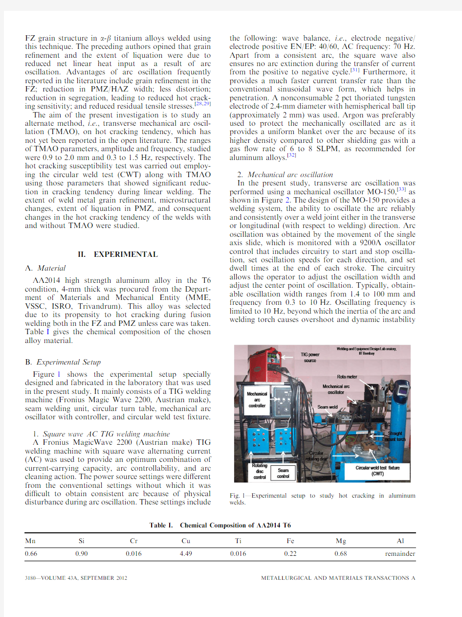
Figure 1shows the experimental setup specially designed and fabricated in the laboratory that was used in the present study.It mainly consists of a TIG welding machine (Fronius Magic Wave 2200,Austrian make),seam welding unit,circular turn table,mechanical arc oscillator with controller,and circular weld test ?xture.1.Square wave AC TIG welding machine
A Fronius MagicWave 2200(Austrian make)TIG welding machine with square wave alternating current (AC)was used to provide an optimum combination of current-carrying capacity,arc controllability,and arc cleaning action.The power source settings were di?erent from the conventional settings without which it was di?cult to obtain consistent arc because of physical disturbance during arc oscillation.These settings include
the following:wave balance,i.e.,electrode negative/electrode positive EN/EP:40/60,AC frequency:70Hz.Apart from a consistent arc,the square wave also ensures no arc extinction during the transfer of current from the positive to negative cycle.[31]Furthermore,it provides a much faster current transfer rate than the conventional sinusoidal wave form,which helps in penetration.A nonconsumable 2pct thoriated tungsten electrode of 2.4-mm diameter with hemispherical ball tip (approximately 2mm)was used.Argon was preferably used to protect the mechanically oscillated arc as it provides a uniform blanket over the arc because of its higher density compared to other shielding gas with a gas ?ow rate of 6to 8SLPM,as recommended for aluminum alloys.[32]
2.Mechanical arc oscillation
In the present study,transverse arc oscillation was performed using a mechanical oscillator MO-150,[33]as shown in Figure 2.The design of the MO-150provides a welding system,the ability to oscillate the arc reliably and consistently over a weld joint either in the transverse or longitudinal (with respect to welding)direction.Arc oscillation was obtained by the movement of the single axis slide,which is monitored with a 9200A oscillator control that includes circuitry to start and stop oscilla-tion,set oscillation speeds for each direction,and set dwell times at the end of each stroke.The circuitry allows the operator to adjust the oscillation width and adjust the center point of oscillation.Typically,obtain-able oscillation width ranges from 1.4to 100mm and frequency from 0.3to 10Hz.Oscillating frequency is limited to 10Hz,beyond which the inertia of the arc and welding torch causes overshoot and dynamic instability
Table I.Chemical Composition of AA2014T6
Mn Si Cr Cu Ti Fe Mg Al 0.66
0.90
0.016
4.49
0.016
0.22
0.68
remainder
Fig.1—Experimental setup to study hot cracking in aluminum welds.
of the system while welding.The main advantage of MO-150is its design to handle most of the welding processes,including TIG,plasma,and MIG and the feasibility of use in the manufacturing environment.This mechanical oscillator can also be used in weaving the arc for surfacing or stitching of plates.
Oscillation of the welding arc is a function of amplitude and frequency exerted on it by external means,i.e.,via a mechanical oscillator.In the case of arc oscillation,oscillation parameters (amplitude,fre-quency,and dwell time)were the most important parameters,which were reported in the published literature.[30–34]However,in the present case of TMAO only,amplitude and frequency were considered keeping zero dwell time.
3.Circular weld test
Figure 3shows a schematic design of the CWT along with standard specimen.The design of the test setup used in the present study was similar in design to the CPT used by Huang and Kou [10]and Nelson et al .[16]The design of the CWT depends upon various test conditions.The restraint condition during the test can be imposed by a number of variables such as specimen size,thickness,and depth of the groove (nonautogenous welds).However,in the present case,these variables are typically selected prior to testing,such that they represent the restraint conditions of interest and usually do not change.
During CWT,the specimen is highly restrained (by being bolted down to a thick stainless steel plate)to prevent it from contracting freely during welding.The specimen is sandwiched between a copper plate at the bottom and a copper ring at the top.The copper plate was 1529152919mm.The copper ring was 19-mm thick,with an 83-mm inside diameter,and had dimen-sions of 1529152mm on the outside.The specimen,together with the copper plate and the copper ring,was bolted down tightly to a 25.4-mm-thick stainless steel base plate 2039203mm.The bolts at the center and each corner of the specimen were tightened with a torque wrench to ensure uniform well-de?ned restraint
on the specimen.The specimen was actually separated from the copper plate and ring with washers;without the washers,it was di?cult to produce full penetration welds because of the heat-sink e?ect of copper.C.Experimental Procedure
Experiments were carried out in two stages:(1)auto-genous linear welding with and without TMAO to arrive at a favorable set of oscillation parameters and (2)eval-uation of hot cracking susceptibility by employing a standard CWT with and without TMAO on 4-mm-thick AA2014T6plates using the previously arrived arc oscillation conditions.
1.Autogenous linear welding
Linear weld prepared with the welding parameters given in Table II (a)produced full penetration weld with signi?cant cracking in the FZ.[35]Using these welding parameters,several welds approximately 100mm in length were prepared with di?erent combinations of arc oscillation parameters.The arc oscillation parameters used were in the amplitude range of 0.9to 2.0mm and frequency range of 0.3to 1.5Hz.
2.Circular weld test
Hot cracking susceptibility testing was carried out by employing CWT without and with TMAO,using those parameters that resulted in crack-free linear welds.This was done to verify whether favorable results obtained in linear welds could be maintained at higher restraint stress levels.In the present study,instead of using a circular patch (usually for nonautogenous welds),a circular weld of 50-mm diameter was prepared on a standard test specimen and will be referred to as the CWT in the remainder of
the
Fig.2—Typical mechanical oscillator (MO-150)used to produce TMAO.[33
]
Fig.3—Schematic of circular weld test:(a )standard test specimen and (b )CWT ?xture.[16]
text.Welding parameters used for CWT given in Table II(b) were di?erent in value as compared to linear welds as circular welding speed was adjusted to obtain full penetration to avoid excess melting.Weld prepared with smaller diameter(30mm)produced excess penetration and melting,while larger diameter weld of60mm showed less cracking tendency with reduced penetration.On the other hand,the weld prepared with50-mm diameter produced full penetration with signi?cant cracking in the FZ,and the same was used for the circular weld test with and without TMAO.
For CWT with TMAO parameters(0.9-mm ampli-tude and0.5-Hz frequency)was used speci?cally as these combination showed higher crack resistance during linear welding.The reason for the same is explained in the subsequent Section III–A.
Prior to welding,the standard test specimens were mechanically brushed with a wire brush to remove the tenacious oxide formed on the surface and further thor-oughly cleaned with acetone before?xing in the circular patch?xture.The?xture was mounted horizontally on a circular turntable to allow rotation under a stationary straight mount TIG torch attached to the mechanical oscillator.Appropriate external restraint stresses were applied with the help of a torque wrench(51N m, according to the design stress for the unwelded alloy based on the weld tensile strength per British standard code of practice C1181969).[28]Autogenous AA2014TIG circular welds of50-mm diameter were made in a fully automatic Square wave AC TIG welding machine with an attachment of commercially available mechanical arc oscillation equipment(mechanical oscillator MO-150).
Visual inspection was carried out to evaluate quanta-tively hot cracks initially with the help of high magnifying lens;each crack was characterized as(centerline or transverse)and is represented on the overview macro-graph,as shown in Figure5.Second,the length of the uncracked portion of the weld length was determined. The angular uncracked quantity refers to that portion of the weld in which no continuous surface breaking center-line cracking is present.Finally,crack length was measured by placing a protractor on the sample and measuring the length in degrees directly from the as-welded surface of the sample after thorough cleaning.The angular cracked region(cracked length)was used as the index in the assessment of cracking susceptibility in this study.Once cracking was characterized and recorded,the weld bead aspect penetration(D)and bead width(W)were measured and the cross-sectional area(CSA)of the weld was determined using a stereo-microscope.
Microstructural characterization was limited to CWT welds only.The resultant welds were sectioned(transverse) to the welding direction using an abrasive cutter to the required size and shape for metallographic examinations. Both transverse and planer sections of the weld surface were polished using a standard metallographic procedure, followed by polishing(on cloth using alumina slurry and diamond polished with1-l m diamond paste)and etching. Specimens were dip etched(20seconds)with Keller’s reagent(3pct HCL,5pct HNO3,2pct HF,and190mL of H2O)to reveal the microstructure.Microstructures of the specimens were studied under optical microscope (Olympus GX51,I R Technology Services Pvt.Ltd., Mahape,Navi Mumbai,India)and scanning electron microscope(Hitachi S-3400N,Forevision Instruments(I) Pvt.Ltd.,Hyderabad,Andhra Pradesh,India)at15kV. Image analysis of micrographs of the weld metal was carried out using image analyzing software(OLYSIA m3, Olympus,London,United Kingdom).
III.RESULTS AND DISCUSSION
A.Linear Welding
Figure4shows the e?ect of TMAO on the cracking tendency of AA2014autogenous linear welds prepared with and without TMAO.Solidi?cation cracking in the FZ and no visible liquation cracking in the PMZ were observed in the weld prepared without arc oscillation.It is seen that as compared to weld prepared without arc oscillation,all welds prepared with TMAO showed reduced solidi?cation cracking sensitivity.The reduc-tion,however,depended on the combination of fre-quency and amplitude of arc oscillation used.It is well reported that transverse arc oscillation leads to grain re?nement.[25–29]One of the reasons for the grain re?nement was attributed to an increase in cooling rate as a result of reduced heat input.[26,28]In the present case,e?ective net heat input was reduced due to an increase in e?ective welding speed as a result of TMAO. Accordingly,the e?ective welding speed for ampli-tude=0.9mm and frequency=0.5Hz)works out to be4.02mm/s,which is0.4mm/s higher than the actual
Table II.Welding and TMAO Parameters for Both Autogenous Linear and CWT of AA2014T6Alloy
Welding Parameters Mechanical Arc Oscillation Parameters Range
(TMAO)
Current(Amps)Speed(mm/s)Voltage
(V)Amplitude(mm)Frequency(Hz)
(a)Linear welding
165 3.613.4without oscillation
165 3.613.4(0.9to2.0)(0.3to1.5) (b)CWT
175 5.313.4without oscillation
175 5.313.40.90.5
linear welding speed (3.6mm/s).As a result,the cooling rate in TMAO welds was 20pct higher than that of unoscillated welds.The cooling rate was calculated using the empirical equation used for calculating weld thermal cycle parameters.[45]Since full penetration welds were prepared,the equation pertaining to a thermally thin body was used (the Appendix provides the calcu-lation).This,however,cannot be the only reason as the reduction in cracking sensitivity does not show mono-tonic dependence on the reduction in e?ective net heat input,which in?uences the weld cooling rate.Note that at a given frequency,the e?ective net heat input reduces with increasing amplitude and vice versa .
Garland,[30]by employing torch vibration parallel to welding direction (frequency of 10Hz and amplitude 1.2mm),found a reduction in crack length while TIG welding of 3.2-mm-thick Al-1.7-2.8pct Mg aluminum alloy.The reduction in crack length was attributed to extensive grain re?nement due to longitudinal torch vibration.He opined that grain re?nement was the result of back washing of the weld pool over the solid-liquid interface,which periodically fragmented and reoriented the substructure composing the trailing end of the weld pool,to yield in situ the necessary supply of nucleants,which act as grain re?ning agents.
Similarly,Kou [17]showed signi?cant reduction in crack-ing sensitivity when transverse electromagnetic arc oscil-lation (amplitude =1.9mm and frequency =1Hz)was employed during TIG welding of AA2014aluminum alloy.They argued that transverse arc oscillation frequency produced an alternating orientation of the columnar grains,leading to winding of the crack length and making it di?cult to propagate further.
In the present work,microstructural evidence,as shown in Figures 9and 10(for CWT welds as micro-structural characterization was limited to CWT only),supports the view that TMAO leads to breaking up of columnar structures to form equiaxed structures.Crack-ing sensitivity was least (restricted to crater)for welds prepared with amplitude of 0.9mm and frequency of 0.5Hz.This should be attributed to the fact that due to transverse arc oscillation,there is a constructive inter-ference in the solidi?cation process.This constructive interference is maximum at observed TMAO parameters (amplitude =0.9mm and frequency =0.5Hz).Such an
action is required mainly along the narrow region around the weld centerline.Transverse arc oscillation amplitude of 0.9mm roughly corresponds to 21pct of FZ width (8.7mm).Note that the ?rst approximation weld solid-i?cation rate (R )is given by (u cos h ),where u is the linear welding speed and h is the angle between the normal at the point on the interface in the welding direction.[17]That is why amplitudes greater than a particular value lead to reduction in the bene?cial e?ect of TMAO.
The useful amplitude,over which TMAO will be bene?cial,will be decided by both the weld pool size and shape of the trailing edge.These,in turn,will depend on the primary welding parameters,linear welding speed,and welding current.As far as arc oscillation frequency is concerned,it is likely that it will depend on the linear welding speed.In the case of full penetration welds with substrate plates of di?erent thicknesses,it is quite possible that the optimum combination of TMAO may be di?erent.This is because di?erent thicknesses require di?erent welding parameters,leading to di?er-ences in the weld pool size and shape.Thus,the observed reduction in cracking sensitivity can be attrib-uted to mechanical agitation and an increase in cooling rate,both of which lead to grain re?nement.B.Circular Welding Test
Figure 5shows the overview of the macrographs of CWT welds prepared with and without arc oscillation.For better visibility,the crack path observed was traced with a dark line.From the overview of the top surface,many transverse cracks before the centerline cracks were seen,which were very minute and di?cult to quantify.The circumferential length corresponding to the chosen diam-eter of the weld was 50mm;the total crack length was expressed in terms of angle covered remembering that 360deg approximately corresponds to a length of 160mm.As many as three centerline cracks at di?erent locations of the weld were observed;and these accumulated for a total crack length of 48.5mm i.e.,30%of cracking in weld prepared without oscillation.However,it should be noted that these centerline cracks originated from the PMZ region,indicating transverse liquation cracking,but there was no longitudinal PMZ cracking along the circumferen-tial length of the weld.It also should be noted that as compared to linear welds,which did not show any PMZ cracks with or without arc oscillation,CWT has shown indications of PMZ cracking in addition to FZ cracking in CWT welds prepared without arc oscillation.However,in arc oscillated welds,these cracks were also eliminated except for small FZ crater cracks,as shown in Figure 5(b).In the present case,for welds without oscillation,cracking was not very severe;this is mainly because the alloy contains a higher weight percent (4.45)of Cu,which lies in the less crack sensitive region of the curves of the hot cracking sensitivity of aluminum alloys.[36]However,alloy AA2014also contains a small amount of Mg,which depresses the solidus temperature,but it does not a?ect the coherence temperature;therefore,the coherence range extends and the hot cracking tendency increases.It is interesting to note that solidi?cation cracking and liquation cracking did not co-exist,i.e.
,
Fig.4—E?ect of TMAO parameters on AA2014autogenous linear welds:amplitude (0.9to 2.0mm)and frequency (0.3to 1.5Hz).
side by side,as seen from Figure 5(a).It is also evident that liquation cracking stopped at the point where solidi?cation cracking started.This is probably because solidi?cation cracking in the weld metal signi?cantly relaxed the residual tensile strains in the adjacent PMZ.Similar incidences of absence of co-existence of liqua-tion and solidi?cation cracking were reported when the AA2219alloy was welded with di?erent ?ller (1100,110A,and 2219)during TIG welding with CPT.[10]
CWT frequently causes cracking because of the design of the test and specimen as both the FZ and HAZ are subjected to higher tensile stresses.[37]The greater the radius of the circular weld,the lower the additional improved tensile stresses.On the other hand,a smaller weld size corresponds to a higher restraint.The cracking tendency is inversely related to the radius of the circular weld.[37]
Transverse liquation cracks were seen only along the outer edge of the weld,but there was no liquation cracking either transverse or longitudinal along the inner edge.In CWT,the specimen is held tightly against a strong back (the stainless steel base plate,as shown in Figure 3).This keeps the weld metal from contracting due to thermal contraction and solidi?cation shrinkage when it cools.[10]As a result,the outer edge of the weld experiences tensile stress because of the restrained stresses from all four corners,while the inner edge is subjected to compressive stress as opposed by the substrate from the weld center.This explains why transverse liquation cracks were observed only along the outer edge of the weld.
Figure 5(b)shows the overview macrograph of weld prepared with TMAO parameters:(ampli-tude =0.9mm and frequency =0.5Hz).No trace of any solidi?cation cracks,except a small crater crack at the end of the weld,was observed.The weld bead appeared to be wider (8.74mm)with reduced depth (4.01mm)as compared to without oscillation (width of 7.85mm and higher depth of 4.08mm),with smooth weld surface demonstrating the bene?cial e?ect of TMAO in reducing hot cracking tendency.The elimination of cracking was attributed to grain
re?nement and reduced amount of segregation along the interdendritic regions as a result of reduced linear e?ective net heat input,which is explained in Section III–C–1.
1.Hot cracking sensitivity
Generally,weld metal solidi?cation cracking in alu-minum alloys occurs when higher levels of thermal stresses and solidi?cation shrinkage are present during welding.[17]It is in?uenced by a combination of mechanical,thermal,and metallurgical factors.In practice,the solidi?cation cracking sensitivity of alumi-num alloy weldments is determined by the chemical composition and welding conditions.The usual methods of eliminating cracking in aluminum welds are to control the weld metal composition (using overalloyed ?ller,which facilitates back ?lling)and to use low heat input,such as use of arc oscillation techniques.[26–28]However,in the present case,weld metal composition control was beyond the scope due to autogenous welding,and the latter was obtained by employing TMAO.Figure 6illustrates the e?ect of TMAO on e?ective net heat input for a given amplitude of 0.9mm (the Appendix provides the calculation).The cracking sensitivity in aluminum welds is shown schematically and discussed.
Figure 7illustrates the weld top surface and trans-verse cross section of the welds prepared with and without TMAO,respectively.It is clear that the TMAO weld (Figures 7(b)and (d))has the higher cracking resistance (no cracks)as compared to that without oscillated weld (Figures 7(a)and (c)),which experienced cracking.Stress concentration in the welded joint of the aluminum alloy is induced in two ways:thermal stress,due to the high coe?cient of thermal expansion,and large solidi?cation shrinkage,almost twice that of steel.In normal welding processes,i.e.,without transverse arc oscillation,the FZ typically is V shaped,as shown in Figure 8(a).Shrinkage forces within the V-shaped zone cause the plate to have an angular distortion.
The
Fig.5—Overview of macrographs of CWT showing crack morphology:(a )without oscillation and (b )with TMAO (amplitude =0.9mm and frequency =0.5Hz).
shrinkage-induced stresses increase from the bottom to the top surface,[38]as shown in Figure8(a).If the plate is constrained during welding,the distortion will decrease; however,the residual stress in the weld zone will greatly increase.
On the contrary,TMAO weld showed improved bead morphology similar to the schematic shown in Figure 8(b)with increase in weld width;8.74mm at the top and 7.0mm at the root as compared to7.85mm and4.2mm width at the top and root of the weld,Figure7(c)and(d);consequently,increasing the weld metal cross-sectional area i.e.,28.00mm2as compared to 20.01mm2in case of weld prepared without oscillation. However,the weld bead morphologies depend on the oscillation parameters:amplitude and frequency.It is observed that,at lower frequency,the bead shape seems to be wide as compared to that at high frequency.[39] This means that there is a de?nite change in concentra-tion of shrinkage forces,which nearly approaches uniform at both the top and bottom of the weld zone during cooling,as seen in Figure8(b),and better
resists Fig.6—E?ect of TMAO parameters on e?ective net heat input
(amplitude=0.9
mm).
Fig.7—Weld bead morphologies of CWT autogenous AA2014welds:(a)and(c)without oscillation and(b)and(d)with TMAO(amplitude= 0.9mm and frequency=0.5
Hz).
Fig.8—Schematic of the shrinkage forces in aluminum autogenous
TIG welds:(a)without and(b)with TMAO.[21]
cracking.Thus,from the observed results and based on the earlier reported observation,[21]it can be said that TMAO helps reduce the cracking sensitivity of the alloy during welding.
C.Microstructure Analysis
1.Weld metal solidi?cation structure
The weld metal solidi?cation microstructure is another critical factor in?uencing cracking sensitivity in aluminum alloy weldments.[40,41]In autogenous welding,the grain structure is controlled by a combination of the thermal conditions that prevail at the solid-liquid interface and the crystal growth rate,which is directly related to the welding speed.[42]The thermal conditions are determined by the heat input and the weld speed for a given sheet thickness.Furthermore,the conditions vary considerably depending on the position at the solid-liquid interface along the trailing edge of the weld pool.[17]
Two di?erent types of grain structures were observed,as a function of the welding conditions,i.e.,with and without arc oscillation.Figures 9(a)and (c)represent the grain structure of weld without arc oscillation,and Figures 9(b)and (d)that of the weld prepared with TMAO (amplitude of 0.9mm and frequency of 0.5Hz).As shown in Figure 9(b),the arc oscillated weld
produced equiaxed grain with average grain diameter of 23.30l m with fragmented interdendritic arms at the weld centerline,as compared to coarse grains measuring 30.35l m and darkly etched dendritic structures with continuous interdendritic arms in weld prepared without TMAO (Figure 9(a)).On either side of the equiaxed grains,columnar-dendritic grains were found,which solidi?ed on the base metal epitaxially and grew toward the central axial region.The epitaxially grown dendrites were curved toward the heat source,as shown in Figure 9(c),so that the maximum thermal gradients,G ,present at the solid-liquid interface,are maintained as growth proceeds without oscillated welds.Furthermore,the lower welding speed (5.3mm/s)results in a lower solidi?cation rate,R .[26,42]With high-temperature gra-dient,G ,and small growth rate,R ,the alloy solidi?ca-tion microstructure consists of columnar dendritic grains,[17,43]as is observed in Figure 9(c).
On the contrary,the epitaxially grown dendrites were straight and smaller in size,as shown in Figure 9(d),in the weld prepared with arc oscillation.Furthermore,the higher e?ective welding speed (5.6mm/s)causes the e?ective net heat input to be small,[17]which results in smaller temperature gradient,G .Also,the increase in e?ective welding speed during arc oscillation leads to an increase in solidi?cation rate,R .[17]For
smaller
Fig.9—Comparison of autogenous AA2014T6CWT welds:(a )and (c )without (b )and (d )with TMAO (parameters:amplitude =0.9mm and frequency =0.5Hz).
temperature gradients,G ,and larger solidi?cation rates,R ,the alloy solidi?cation microstructure consists of equiaxed grains at the center and straight columnar grains toward the fusion boundary.[17,43]It is reported that transverse arc oscillation (electromagnetic)produces equiaxed grains in the weld metal.[26,27]Similar grain structure was observed,as illustrated in Figures 9(b)through (d).It is clear that grain re?nement is possible with TMAO;however,its extent will depend upon the oscillation parameters.2.Effect on subgrain structure
Figure 10shows the SEM microstructures taken at the weld center and near the fusion boundary for welds made with and without arc oscillation.It is seen that the subgrains’structure is signi?cantly modi?ed in the TMAO weld compared to that in the weld without arc oscillation.This is attributed to the increase in cooling rate as a result of transverse arc oscillation,as explained below.
According to the principle of solidi?cation process-ing,[36,44]the higher the cooling rate is during solidi?ca-tion,the ?ner the resulting subgrains’structure.This is because higher cooling rates allow less time for the coarsening of the subgrains to occur during solidi?cation.
Similar modi?ed microstructures were observed in welds prepared with transverse electromagnetic arc oscillation with amplitude of 1.9mm and frequency of 1Hz.[26]Subgrain re?nement in the case of transverse arc oscillation was explained by Kou.[17]According to Figure 11,in the case of weld with TMAO,the weld pool has two velocity components:one in the
welding
Fig.10—Comparison of subgrain structure between welds prepared with and without TMAO:(a )weld center and (b )near FZ boundary;at amplitude of 0.9mm and frequency of 0.5
Hz.
Fig.11—E?ect of arc oscillation on welding speed.[17]
direction(u)and the other transverse to the welding direction(v).The resultant velocity(w),of course,is greater than the velocity of the non-oscillated weld pool(u).
The welding speed for the weld without oscillation is u=5.3mm/s.On the other hand,for the oscillated weld with amplitude0.9mm and frequency0.5Hz, v=1.8mm/s,which means the arc travels (0.99490.5=1.8mm/s)transverse to the welding direction.Therefore,the resultant welding speed,w,is 5.6mm/s,which is0.3mm/s higher than the non-oscillated weld;consequently,it produces higher cooling rate during solidi?cation,resulting in?ner subgrain structure in the TMAO weld.
3.PMZ structure
PMZ is the region of weld located immediately adjacent to the fusion boundary.It is the area where the peak temperature during welding is below the liquidus temperature and above the solidus,and it is characterized by melting of the eutectic material, particularly along the grain boundaries.As shown in Figure12(b),the extent of grain boundary melting is less severe in the TMAO weld as compared to the weld without oscillation(Figure12(a)).Furthermore,a sig-ni?cant reduction in the partially melted region was also observed,as shown in Figure12(b).This could be attributed to an increase in cooling rate due to reduced e?ective heat input as a consequence of arc oscillation. The extent of melting in the adjacent PMZ and its size depend upon the kinetic strength of the weld thermal cycle.The thermal cycles that cause partial melting have peak temperatures lower than those that cause complete melting in the FZ,but above those that do not cause melting but a?ect the microstructure of the solid surrounding the FZ.The extent of liquation along the GBs appears to be higher in welds prepared without TMAO(Figure12(a)).
Figure13illustrates the extent of PMZ width formed in welds prepared with and without TMAO.PMZ width was measured from the FZ boundary to a distance where grain boundary(GB)liquation was observed clearly under optical microscope.Figure13(b)shows the average width of the PMZ in TMAO welds,which is relatively narrower, i.e.,1.88mm,and approximately25pct lesser than that
of Fig.12—Comparison of grain boundary melting in the PMZ between two welds made without and with TMAO at amplitude=0.9mm and 0.5
Hz.
Fig.13—E?ect of TMAO on PMZ width:(a)for welds prepared without oscillation and(b)with TMAO.
the weld prepared without oscillation,as shown in Figure13(a),measuring2.52mm.
Figure14(a)shows the PMZ microstructure of weld prepared without TMAO,where incidences of liquation cracks in the PMZ were observed as noticed from the overview macrograph(Figure5(a)).The formation of liquation cracks is due to the formation of thin liquid?lm along the GBs because of the melting of low melting elements.First,this liquid eutectic upon resolidi?cation forms solid eutectic,which is mechanically weak(a combination of hard and soft phases)and can cause severe loss in ductility during PMZ solidi?cation.Second,the formation of tensile strains due to external restraint stresses from all four corners and the center of the weld specimen.It should be noted that in the present case no continuous circumferential(longitudinal)liquation cracks were ob-served because of the relaxation in residual tensile stress due to solidi?cation cracking in the FZ.Such a crack in the adjacent PMZ observed is shown in Figure14(a).How-ever,in the case of TMAO weld,no such incipient cracks were seen in the PMZ,as shown in Figure14(b).
IV.CONCLUSIONS
The e?ect of TMAO on the hot cracking behavior of autogenous AA2014T6aluminum alloy TIG welds was investigated.
1.Hot cracking susceptibility with CWT demonstrated
that AA2014aluminum alloy in T6is prone to hot cracking,i.e.,solidification cracking in the weld me-tal and liquation cracking in the PMZ.
2.During normal welding(without arc oscillation),
solidi?cation cracking accounted for30pct of the total length of the weld;however,transverse liquation cracks were di?cult to quantify as they just initiated and terminated as solidi?cation cracks occurred.
3.TMAO weld showed higher hot cracking resistance.
Oscillation parameters,amplitude0.9mm and fre-quency0.5Hz,proved to be bene?cial in eliminat-ing solidi?cation cracks,except some crater cracks,and ensuring complete absence of transverse
liquation cracking.The preceding improvements were attributed to the following.
(a)An increase in solidi?cation cracking resistance
due to TMAO is a result of weld metal grain
re?nement with signi?cant modi?cations in the
subgrain structure.
(b)The complete elimination of liquation cracks in
the PMZ is due to reduced extent of grain bound-
ary liquation and consequent reduction in PMZ
width.
(c)Change in bead morphology resulting in unifor-
mity of residual tensile strains also helped in
reducing cracking tendency.
4.The preceding obtained results were comparable
with those obtained for transverse electromagnetic arc oscillation used in autogenous welds of AA2014 alloy reported in the literature.[26]
5.TMAO obviously appears to be a potential alterna-
tive method of arc oscillation to mitigate hot crack-ing in fusion welds.
ACKNOWLEDGMENTS
The authors thank the Indian Space Research Organi-zation(ISRO,Trivandrum,India)for providing the mate-rial AA2014aluminum alloy in the T6condition necessary for carrying out the experiments in the research study.
APPENDIX:CALCULATION OF EFFECTIVE
WELDING SPEED(W)
w?u2tv2
àá1=2
?3:62t1:82
àá1=2
?4:02mm=s linear welding
eT
?5:32t1:82
àá1=2
?5:6mm=s CWT welding
eT
where u=linear welding speed(3.6mm/s for linear welding and 5.3mm/s for CWT welding)
and Fig.14—Liquation cracking in the PMZ:(a)without oscillation and(b)with TMAO(amplitude=0.9mm and frequency=0.5Hz).
v=transverse welding speed of the torch in mm/s. E?ective welding speed for the TMAO parameter (amplitude=0.9mm and frequency=0.5Hz): v?0:9?4?0:5
eTfor one cycle of oscillation
?1:8mm=s
HEAT INPUT CALCULATIONS(H NET)USED FOR TUNGSTEN INERT GAS WELDING WITH AND WITHOUT TMAO(AMPLITUDE=0.9MM AND
FREQUENCY=0.5HZ)
For linear TIG welding:
H Net without TMAO
eT
?V?I?g=u
?165?13:4?0:40=3:6
?245:6J=mm
H Net with TMAO
eT
?V?I?g=w
?165?13:4?0:40=4:02
?220J=mm
For CWT TIG welding:
H Net without TMAO
eT
?V?I?g=u
?175?13:4?0:40=5:3
?176:9J=mm
H Net with TMAO
eT
?V?I?g=w
?175?13:4?0:40=5:6
?167:5J=mm
where V=voltage in volts,I=current in Amps, g=arc e?ciency(assumed as0.40for TIG),[32] u=welding speed in mm/s(without arc oscillation),and w=e?ective welding speed due to TMAO in mm/s.
COOLING RATE CALCULATIONS,R,FOR TIG WELDS WITHOUT AND WITH TMAO
(AMPLITUDE=0.9MM AND
FREQUENCY=0.5HZ)
For Linear TIG welding:
R=2p k q C(s/H Net)2(T c–T0)3for thin plates at full penetration were produced.[45]
R without TMAO
eT
?2p?0:23?0:00274=245:6
eT2?911:15à303:15
eT3?505:75K232:6 C=s
eT
R with TMAO
eT
?2p?0:23?0:00274=220
eT2?911:15à303:15
eT3?563:05K289:9 C=s
eT
For CWT TIG welds:
R without TMAO
eT
?2p?0:23?0:00274=176:9
eT2?911:15à303:15
eT3?721:45K448:3 C=s
eT
R with TMAO
eT
?2p?0:23?0:00274=167:69
eT2?911:15à303:15
eT3?771:35K498:2 C=s
eT
where k=thermal conductivity(J/mm2K),q C=ther-mal capacity(J/mm3K),s=thickness of the plate(mm), H Net=e?ective heat input(J/mm),T c=liquidus tem-perature(K),and T0=initial temperature(K).
REFERENCES
1.P.O.Puzak,W.R.Apblett,and W.S.Pellini:Weld.J.,1956,vol.35
(1),pp.9–20.
2.J.E.Steenbergen and H.R.Thornton:Weld.J.,1970,vol.49(2),
pp.61s–68s.
3.F.C.Hull:Weld.J.,1967,vol.46(9),pp.399s–409s.
4.C.E.Cross:Hot Cracking Phenomena in Welds,Springer,New
York,NY,2005,pp.3–18.
5.M.Miyazaki,K.Nishio,M.Katoh,S.Mukae,and H.W.Kerr:
Weld.J.,1990,vol.69(9),pp.362s–71s.
6.S.Kou:JOM,2003,vol.6,pp.37–42.
7.G.J.Davies and J.G.Garland:Int.Met.Rev.,1975,vol.20,
pp.85–105.
8.A.R.E.Singer and P.H.J.Jennings:Inst.Met.,1947,vol.73,
pp.273–84.
9.J.L.Robinson and M.H.Scott:Phil.Trans.R.Soc.London,1980,
vol.A285,pp.105–17.
10.C.Huang and S.Kou:Weld.J.,2004,vol.83(2),pp.50–58.
11.J.C.Lippold:Hot Cracking Phenomena in Welds,Springer-Verlag,
Berlin,Germany,2005,pp.271–90.
12.J.C.M.Farrar:Hot Cracking Phenomena in Welds,Springer,New
York,NY,2005,pp.291–304.
13.H.Heuser:Hot Cracking Phenomena in Welds,Springer,New
York,NY,2005,pp.305–27.
14.E.Cical a,G.Du?et,H.Andrzejewski,D.Grevey,and S.Ignata:
Mater.Sci.Eng.A,2005,vol.395,pp.1–9.
15.G.M.Goodwin:‘‘Test Methods for Evaluating Hot Cracking:
Review and Perspectives,’’Energy Citation Database,Science Accelerator,OTSI,US Department of Energy,1990,pp.1–26. 16.T.W.Nelson,J.C.Lippold,W.Lin,and W.A.Baeslack,III:Weld.
J.,1997,vol.76(3),pp.110–19.
17.S.Kou:Welding Metallurgy,2nd ed.,John Wiley and Sons,New
York,NY,2003,pp.321–24.
18.H.Yunjia,R.H.Frost,D.L.Olson,and G.R.Edwards:Weld.J.,
1989,vol.68,pp.280–88.
19.M.J.Dvornak,R.H.Frost,and D.L.Olson:Weld.J.,1989,
vol.68,p.327s.
20.V.Balasubramanian,V.Ravisankar,and G.Madhusudhan
Reddy:Mater.Sci.Eng.A,2007,vol.2459,pp.19–34.
21.Y.M.Zhang,C.Pan,and A.T.Male:Metall.Mater.Trans.A,
2000,vol.31A,pp.2537–43.
22.J.C.Villafuerte and H.W.Kerr:Weld.J.,1990,vol.69,pp.1s–13s.
23.S.P.Tewari:Thammasat Int.J.Sci.Technol.,2009,vol.14(4),
pp.17–27.
24.S.Kou and Y.Le:Weld.J.,1986,vol.65(12),pp.305–13s.
25.S.Kou and Y.Le:Metall.Trans.A,1985,vol.16A,pp.1345–52.
26.S.Kou and Y.Le:Weld.J.,1985,vol.64(3),pp.51s–55s.
27.S.Sundaresan and G.D.Janakiram:Sci.Technol.Weld.Join.,
1999,vol.4,pp.151–61.
28.C.-F.Tseng and W.F.Savage:Weld.J.,1971,vol.51(11),
pp.777–85.
29.S.R.Koteswara Rao,G.M.Reddy,M.Kamaraj,and K.Prasad
Rao:Mater.Sci.Eng.A,2005,vol.404,pp.227–34.
30.J.G.Garland:Met.Construct.,Br.Weld.J.,1974,vol.55(4),
pp.121–27.
31.TIG Welding Handbook,Miller Electric Mfg.Co.,Appleton,
pp.5–18.
32.Ador Welding Limited:Modern Welding,Oxford and IBH Pub-
lishing Co.Pvt.Ltd.,New Delhi,2005,pp.275–78.
33.Operational Manual MO-150Mechanical Oscillator,Jetline Engi-
neering Inc.,Irvine,CA,pp.5–38.
34.A.Kumar,P.Shailesh,and S.Sundarrajan:Mater.Des.,2008,
vol.29,pp.1904–13.
35.N.S.Biradar,S.Mishra,and R Raman:Materials Research
Symp.-MR-10,IIT Bombay,Bombay,2010,pp.72–73.
36.J.H.Dudas and F.R.Collins:Weld.J.,1966,vol.45,pp.241s–49s.
37.T.-L.Teng,P.-H.Chang,and H.-C.Ko:Int.J.Pressure Vess.Pip.,
2000,vol.77,pp.643–50.
38.N.S.Biradar and R.Raman:Proc.IIW Int.Conf.on Joining,
Cutting,and Surfacing Technology, D.V.Kulkarni,Manish
Samant,S.Krishnan,Amitava De,J.Krishnan,H.Patel,and
A.K.Bhaduri,eds.,Chennai,2011,pp.371–79.
39.ASM Specialty Handbook:Aluminum and Aluminum Alloys,J.R.
Davis,ed.,ASM INTERNATIONAL,Materials Park,OH,1994, pp.376–419.
40.J.A.Brooks and J.J.Dike:Proc.5th Int.Conf.on International
Trends in Welding Research,Pine Mountain,GA,June1998,ASM INTERNATIONAL,Materials Park,OH,1999,pp.695–99. 41.D.M.Douglass,J.Mazumder,and K.Nagarathnam:Proc.4th
Int.Conf.on Trends in Welding Research,Gatlinburg,TN,June 1995,pp.467–78.
42.K.Easterling:Introduction to Physical Metallurgy of Welding,
Butterworth and Co.Ltd.,Mosco,1983,pp.55–66.
43.L.F.Mondolfo:Aluminum Alloys Structure and Properties,But-
terworth and Co,London,1976,pp.693–700.
44.M.C.Flemings:Solidi?cation Processing,McGraw-Hill,New
York,NY,1974,pp.73–83.
45.R.W.Messler,Jr.:Principles of Welding,John Wiley and Sons,
Inc.,New York,NY,1999,pp.175–76.
01-文献综述范文-翻译-当前零翻译研究问题与对策
外国语学院2018届毕业论文文献综述(示范) 一、研究背景 近来多篇论文中出现零翻译的提法(杜争鸣,2000;邱懋如,2001;刘明东,2002;袁斌业,2002a,2002b,2002c,2002d;石琳,2003;余清萍,2003;余清萍,秦傲松,2004;肖耀田,2004),但国内学者所编三本译学词典(林煌天,1997;孙迎春,1999;方梦之,2004)均未出现零翻译这一词条,国外三本词典/术语著作(Shuttleworth & Cowie,1997;Baker,1998;Delisle,2004)亦未收入这一条目,只有国内孙迎春(2001)编著的《汉英双向翻译学语林》收进了“零翻译(音译、形译之一种)zero translation”(58页)及“zero translation零翻译(音译、形译之一种)”(268页)两个条目,同时又有贾影(2002)反对零翻译提法,并认为承认不可译有“积极作用”。但零翻译现象确实存在,如DIY(自己动手),IQ(智商),EQ(情商),这些零翻译词汇经常在汉语中出现。英语中也有类似情况,如美国《时代》周刊中报道中国特色事物时经常使用拼音,如aizi(矮子),pizi(痞子),shiganjia(实干家),yuan(缘)(王祥兵,2002),shuangying(双赢),guanxi(关系)(顾静,2005)。 这些研究成果揭示了零翻译现象的存在,引进了零翻译的概念,促进了翻译理论概念的扩大,但是从发表的论文及孙迎春(2001)的这两个条目来看,各自运用的名称虽同(也有不同,如杜争鸣称为不译),但概念的内涵及外延均有出入,因此有必要探讨当前零翻译研究的问题并提出相应研究对策。 二、研究现状及不足 1. 定义不统一、模糊不清 传统翻译理论多把零翻译归结为“音译法”、“移译法”,只看到技巧层面的意义,如秦建栋(1999)讨论“英汉词汇空缺现象刍议”列举“音译法”、“移译法”,袁斌业(2001)论及“英语本族人音译汉语词汇的语用分析”,虽然看到“音译在我国只能用来翻译名词,而在国外则可以用来翻译包括名词在内的各种词语”,但未能从中提炼出零翻译的概念,实际上这里已包含有零翻译与音译的某些区别。 国内最早使用zero translation这一术语的是杜争鸣(2000),但他称之为“不译”,并分析了直译、意译与不译三种翻译策略。他不停留于策略本身,从跨文化交际的视角分析了三种策略的社会语言学与跨文化交际涵义,并看到了不译的三层文化含义。不译背后体现译者对于翻译目的的认识,“而翻译的目的必然直接或间接地反映反映译者本人对翻译的文化含义的意识与潜意识,反映他翻译时所采取的文化姿态与立场。”即翻译观的问题。但从术语的精确性来说
焊接方法与几种焊材的中英文对照
焊接方法与几种焊材的中英文对照 自己在工作中总结出了几种焊接方法和焊材的英文名称,看大家是否用得上 MIG --------------Metal Inert Gas arc welding ----------熔化极惰性气体保护电弧焊MAG--------------Metal Active Gas arc welding----------熔化极活性气体气体保护电弧焊TIG --------------Tungsten Inert Gas Welding--------------钨极惰性气体保护焊SAW——Submerged Arc Welding——埋弧焊 其它: FCAW——flux cored arc welding——药芯焊丝电弧焊 FCW-G——gas-shielded flux cored arc welding——气保护药芯焊丝电弧焊 FCW-S——self-shielded flux cored arc welding——自保护药芯焊丝电弧焊GMAW——gas metal arc welding——熔化极气体保护电弧焊 GTAW——gas tungsten arc welding——钨极气体保护电弧焊 焊材与焊接常用词汇: 焊丝welding wire. Welding rod 实心焊丝solid wire 镀铜焊丝copper-plating welding wire 或copper-coating welding wire 药芯焊丝flux-cored wire 填充焊丝filler wire 焊条electrode/ covered electrode 酸性焊条acid electrode 高钛型焊条high titania (type) electrode 钛钙型焊条lime titania type electrode 钛铁矿形焊条ilmenite type electrode 氧化铁型焊条iron oxide type electrode/ high iron oxide type electrode 高纤维素型焊条high cellulose (type) electrode 石墨型焊条graphite type electrode 碱性焊条basic electrode/ lime type covered electrode 低氢型焊条low hydrogen type electrode 高韧性超低氢焊条high toughness super low hydrogen electrode 奥氏体焊条austenitic electrode
焊接 翻译
Welding There are a number of methods of joining meta l articales together,dep ending on the type of meta l and the strength of the joint which is reqired. Soldering gives a satisfactory joint for light articles of steel,copper or brass. but the strength of a soldeing is rather less than a joint which is brazed,ri veted or welded.These methods of jointing meta l are normally adopted for srtong permanent joint. The simplest method of welding two pieces of meta l toghter is known as pressure welding.The ends of meta l are heated to a white heat-for iorn, the welding temperature should be about 1300℃-in a flame.At this tempera ture the meta l becomes plastic.The ends are then pressed or hammered tog ether,and the joint is stoothed off.Care must be taken to ensure that the su rface are thoroughly clean first,for dirt will weaken the weld.Moreover, the heating of iron or steel to a high temperature causes oxidation,and a firm of oxide is formed on the heated surfaces.For this reason,a flux is applied to the heated meta l.At welding heat,the flux meta ls,and oxide particles are dissolved in it together with any other imputities,and the flux is squeezed out from the center of the weld.A number of different types of weld may be used ,but for fairly thick bars of meta l,a vee-shaped weld should norm ally be employed.It is rather stonger than the ordinary butt weld. The heat of fusion welding is generated in several ways,depending on the sort of meta l which is being welded and on its shape.An extremely h ot flame can be produced from an oxyacetylene torch. For certain welds a n electric arc is used. In this method,an electric current is passed across t wo electrodes,and the meta l surface are placed between them.The electrodes are sometimes made of carbon,but more frequently they are meta lllic. The work itself constitutes one of them and the other is an insulated filler rod. An arc is stuck between the two ,and the heat which is generated melts t he meta l at the weld. A different method, known as spot welding, is usual
学术英语理工类文献综述英文
学术英语 学院名称:材料科学与工程学院学生姓名:张庆飞 学号:7301013016 专业班级:新能源材料与器件131 2015年 6月16 日
The current development of genetically modified crops of China and its safety issues Zhang Qingfei (College of materials science and engineering, Nanchang University, 10001) Abstracts: GM technology as a new, highly efficient genetically modified technology, already widely used in the cultivation of new varieties of field crops. China's transgenic technology started earlier, China's current GM technology level in the forefront of the world, especially made great achievements in the cultivation of new varieties of crops. In this paper, the status quo using gene transfer on Chinese agriculture and safety of transgenic technology are introduced, and the resolve of GM safety issues some thought. On this basis, I made some new ideas of transgenic technology and application of transgenic technology development prospects were discussed. Keywords: GM technology; GM crops; GM safety issues; China Introduction: As the core of the biotechnology giant leap .Transgenic technology is known as the second "green revolution." In 1983, the world's first strain of transgenic tobacco plants marks the arrival of the era of gene transfer plants. In the ensuing decades, genetically modified crops developed rapidly. In 2014, there are 28 countries in the world planted GM crops, the planting area has reached more than 180 million hectares, Chinese genetically modified crops planting area is 3.6 million hectares. With the widespread planting of genetically modified crops, the impact of transgenic technology in agriculture is growing. As the research of GM crops, China has made great achievements in the research of rice and cotton. The development of anything will not be smooth. With the development of GM technology, its security deposit issues also be exposed. The safety of genetically modified crops has been disputed by people, opponents argue that GM crops have great potential risk, it should be resisted. What is more, some people exaggerate the risk of genetically modified crops. Aroused people's fear of genetically modified. In this paper, the people of GM crops concerns, the status of the development of GM crops were elaborated. Besides, security problems of genetically modified crops and their solutions will be discussed. The current development of genetically modified crops in china GM refers to the Technology that use molecular biology method to transfer the artificial separation and some modified biological gene to other species and change the genetic characteristics of the species .Plant transgenic technology is the genetic transformation of plants, making plants to meet human needs in aspects of shape, nutrition and consumer quality. China's biotech crop improvement research began in the 1980s, during the past 30 years, Chinese agricultural and biological high-tech has been developing rapidly. At present, China's hybrid rice, cotton and other advanced in the world. GM technology Applied on cotton, rice and other crops on behalf of China's development status of GM crops. As a cotton producing countries, the industrialization of Chinese insect-resistant cotton has brought huge economic and ecological benefits to Chinese
文献综述 英文
文献综述 大学生时间管理研究——以郑州大学西亚斯国际学院为例 姓名:代永寒学号:20091211205 专业:工商管理班级:工本2班 史蒂芬?柯维的《要事第一》 “要事第一”,顾名思义是指重要的主要的事情要放在第一时间去完成。而在实际工作中我们往往是将认为急迫的紧要的事情放在第一时间完成; 本书通过四个象限来告诉我们如何区分事情的紧急性与重要性,从而告诉我们在平常的工作中应怎样去区分事情属轻属重,以及造成事情紧急性的原因,在平常工作中要注意哪些方面以避免出现紧急事件的情况。 第一象限包括四点:A危机 B 急迫的问题C最后期限迫近的项目 D 会议准备工作等。第一象限显得紧迫与重要,但我们要知道形成第一象限的紧迫与重要主要是因被延误及没有进行计划与预测及计划所致。第二象限包含准备工作、预防、价值、筹划、建立关系、真正的再创造与赋予能力。第二象限属于质量象限,属于重要但不紧迫的事情,但我们必须要去做,因只有这样才能避免出现第一象限包含的情况。第三象限包含干扰、电话;邮件、报告;某些会议;很多临近、急迫的事情及很多流行的活动。第三象限包括“紧急但不重要的事情”,而事实上它易给人造成假象,从而形成第一象限情况。第四象限包含琐事、打发时间的工作、某些电话,解闷,“逃避”行为、无关紧要的邮件及过多地看电视;第四象限属于既不紧急也不重要的事情,它是浪费象限,第四象限中的行为是堕落行为。这四个象限告诉我们如果在办事过程中不是以重要性而是以紧要性为出发点,就会出现第一第三甚至第四象限的情况,在平常的工作中,我们要加以区分,日常工作生活中往往事情越是紧迫,反而说明事情越不重要!像最近存货系统因急着想能早日上线,在运作过程中被卡住,故一心想着去解决软件中存在的问题,而忽略了与其他人员的沟通协调,存货上软件固然重要,但与公司整体运作相比就稍显其次,没合理分配其他人员手头事项,这样会导致其他问题的增多,从而会出现第一第三象限甚至于第四象限的浪费情况。 “要事第一”,告诉我们在日常的工作与生活中要从以下方面着手加以区分、
机械毕业设计英文外文翻译88创建焊接程序
附录A 一、创建焊接程序[焊缝的示教]。 焊接机器人程序编辑 1、打开控制柜上的电源开关在“ON”状态。 2、将运作模式调到“TEACH”→“示教模式下” 1.进入程序编辑状态: 1.1.先在主菜单上选择[程序]一览并打开; 1.2.在[程序]的主菜单中选择[新建程序] 1.3.显示新建程序画面后按[选择]键 1.4.显示字符画面后输入程序名现以“TEST”为新建程序名举例说明; 1.5.把光标移到字母“T”、“E”“S”、“T”上按[选择]键选中各个字母; 1.6.按[回车]键进行登录; 1.7.把光标移到“执行”上并确认后,程序“TEST”被登录,并且屏幕画面上显示该程序的初始状态“NOPCEOO”、“ENDCOOL” 1.8.编辑机器人要走的轨迹(以机器人焊接直线焊缝为例); 2.把机器人移动到离安全位置,周边环境便于作业的位置,输入程序(001); 2.1. 握住安全电源开关,接通伺服电源机器人进入可动作状态; 2.2.用轴操作键将机器人移动到开始位置(开始位置电影摄制在安全病史和作业准备位置); 2.3.按[插补方式]键,把插补方式定为关节插补,输入缓冲显示行中显示关节插补命令,‘M OVJ“→”“MOVJ,,VJ=0.78” 2.4.光标放在“00000”处,按[选择]键; 2.5.把光标移动到右边的速度“VJ=**”上,按[转换]键+光标“上下”键,设定再现速度,若设定速度为 50%时,则画面显示“→MOUVJ VJ=50%”,也可以把光标移到右边的速度,‘VJ=***' 上按[选择]键后,可以直接在画面上输入要设定的速度,然后按[回车]键确认。 2.6.按[回车]键,输入程序点(即行号 0001) 3.决定机器人的作业姿态(作业开始位置的附近) 3.1.用轴操作键,使机器人姿态成为作业姿态,然后移到相应的位置; 3.2.按[回车]键,输入程序点 2(0002); 3.3.保持程序点 2 的姿态不变,移向作业开始位置; 3.3.1.保持程序点 2 的姿态不便,按[坐标]键,设定机器人坐标为直角坐标系,用轴操作键把机器人移到作业开始的位置(在移动前可以按手动速度[高][低]键选择焊枪在示教中移动的速度); 3.3.2.光标在行号 0002 处按[选择]键 3.3.3.把光标移动到右边的速度,VJ=***上按[转换]+光标”上下键,设定再现速度,直到设定的速度为所需速度(也可用光标移到速度 VJ=***上,按[选择]键后,输入需要的速度值,按 [回车]键确认即可); 3.3. 4.按[回车]键,输入程序点 3(行号 0003); 3.3. 4.1.把光标移动到“0003”上,按[引弧]键+[回车]键,输入“引弧”指令(行
图像科学综述 外文翻译 外文文献 英文文献
附录 图像科学综述 近几年来,图像处理与识别技术得到了迅速的发展,现在人们己充分认识到图像处理和识别技术是认识世界、改造世界的重要手段。目前它己应用于许多领域,成为2l世纪信息时代的一门重要的高新科学技术。 1.图像处理与识别技术概述 图像就是用各种观测系统以不同形式和手段观测客观世界而获得的,可以直接或间接作用于人眼而产生视知觉的实体。科学研究和统计表明,人类从外界获得的信息约有75%来自于视觉系统,也就是说,人类的大部分信息都是从图像中获得的。 图像处理是人类视觉延伸的重要手段,可以便人们看到任意波长上所测得的图像。例如,借助伽马相机、x光机,人们可以看到红外和超声图像:借助CT可看到物体内部的断层图像;借助相应工具可看到立体图像和剖视图像。1964年,美国在太空探索中拍回了大量月球照片,但是由于种种环境因素的影响,这些照片是非常不清晰的,为此,美国喷射推进实验室(JPL)使用计算机对图像进行处理,使照片中的重要信息得以清晰再现。这是这门技术发展的重要里程碑。此后,图像处理技术在空间研究方面得到广泛的应用。 总体来说,图像处理技术的发展大致经历了初创期、发展期、普及期和实用化期4个阶段。初创期开始于20世纪60年代,当时的图像采用像素型光栅进行扫描显示,大多采用巾、大型机对其进行处理。在这一时期,由于图像存储成本高,处理设备造价高,因而其应用面很窄。20世纪70年代进入了发展期,开始大量采用中、小型机进行处理,图像处理也逐渐改用光栅扫描显示方式,特别是出现了CT和卫星遥感图像,对图像处理技术的发展起到了很好的促进作用。到了20世纪80年代,图像处理技术进入普及期,此时购微机已经能够担当起图形图像处理的任务。VLSL的出现更使得处理速度大大提高,其造价也进一步降低,极大地促进了图形图像系统的普及和应用。20世纪90年代是图像技术的实用化时期,图像处理的信息量巨大,对处理速度的要求极高。 21世纪的图像技术要向高质量化方面发展,主要体现在以下几点:①高分辨率、高速度,图像处理技术发展的最终目标是要实现图像的实时处理,这在移动
焊接专用英文词汇
焊接专用英文词汇 1.1 焊接方法 焊接方法与设备(Welding process& facility) 手工电弧焊(MAW:manual arc welding) 电弧焊(arc welding)埋弧电弧焊(SAW:submerged arc welding)气焊(gas welding)氩弧焊(argon arc welding) 气体保护电弧焊 CO2保护焊(CO2 shielded arc welding) 熔化焊(GMAW—gas metal arc welding) fusion welding 电渣焊(ESW—electroslag welding) 激光焊(LW—laster welding) 等离子焊(PAW—plasma arc welding) 摩擦焊(FRW—friction welding) 焊接压力焊超声波焊(UW—ultrasonic welding) welding pressure welding 冷压焊(CPW—cold pressure welding)锻焊(FW—forge-welding)对焊butt welding 电阻焊(RW—resistance welding) 缝焊seam welding 点焊spot welding 烙铁钎焊 iron soldering 火焰钎焊 torch brazing/ torch soldering 钎焊炉中钎焊 furnace brazing/ furnace soldering soldering/brazing 盐浴钎焊 saltbath dip brazing (soldering) 真空钎焊 vacuum brazing 堆焊 overlaying welding 平焊 downhand welding/flat welding 横焊 horizontal welding 立焊 vertical welding 仰焊 overhead welding 全位置焊 all position welding/positional welding 半自动电弧焊 Semi-automatic arc welding 钨极惰性气体保护电弧焊 (TIG) tungsten inert-gas arc welding 熔化极惰性气体保护电弧焊(MIG)metal inert-gas arc welding 1.2 焊接设备 电弧焊机 arc welding machine 直流弧焊机 DC arc welding machine 交流弧焊机 AC arc welding machine 交直流两用弧焊机 AC/DC arc welding machine 氩弧焊机 argon arc welding machine 二氧化碳弧焊机 CO2 arc welding machine 埋弧焊机 submerged arc welding machine 焊接机头 welding head 行走机构 traveller 送丝机构 wire feeder 焊丝盘 wire reel
文献综述英文版
Title :Magnetic motor shell stamping process and die design Author:yu Department of Materials "Magnetic motor shell stamping process and die design" literature review Abstract摘要 By read these references and documents, in-depth understanding of the contemporary mold of advanced manufacturing technology and metal forming technology, a number of instances of mold design and the understanding and learning, to further study the method of stamping die design, die design and thus have a directionalguidance.As used in this design and drawing die punching die and so on, through the design of the book related to mold in-depth study, this drawing die and the punching die and so the design methods have shape.These references and documents, the design of low-cost high-accuracy die with directional guidance. Keywords: Mold advanced manufacturing technology Mold Manufacturing Trends Drawing Punching CAE Die Materials Prices Preface前言 As China's economic integration with the world economy, the rapid development of basic industries, mold manufacturing industry is also developing fast.In the current economic situation, people pay more attention to efficiency, product quality, cost, and new product development capabilities.The innovation and development of mold manufacturing concern. 1.1 The history of the development of mold Archaeological discoveries in China, as early as 2,000 years ago, China has been used to make bronze stamping dies to prove that in ancient China stamping die stamping and achievements to the world's leading.In 1953, the Changchun First Automobile Works in China for the first time established a stamping plants, the plant began manufacturing cars in 1958, cover mold.60 years of the 20th century began producing fine blanking dies.In walked a long path of development temperature, the present, China has formed more than 300 billion yuan (not including Hong Kong, Macao and Taiwan statistics) the production capacity of various types of stamping dies. 1.2 Development Status and Trends Die Since reform and opening, with the rapid development of the national economy, the market demand of mold growing.In recent years, the mold industry has been the growth rate of about 15% of the rapid development of industrial enterprises in the ownership of the mold components also changed dramatically, in addition to professional mold factory outside of state-owned, collective, joint ventures, wholly-owned and private has been a rapid development.
at89c52单片机中英文资料对照外文翻译文献综述
at89c52单片机简介 中英文资料对照外文翻译文献综述 A T89C52 Single-chip microprocessor introduction Selection of Single-chip microprocessor 1. Development of Single-chip microprocessor The main component part of Single-chip microprocessor as a result of by such centralize to be living to obtain on the chip,In immediate future middle processor CPU。Storage RAM immediately﹑memoy read ROM﹑Interrupt system、Timer /'s counter along with I/O's rim electric circuit awaits the main microcomputer section,The lumping is living on the chip。Although the Single-chip microprocessor r is only a chip,Yet through makes up and the meritorous service be able to on sees,It had haveed the calculating machine system property,calling it for this reason act as Single-chip microprocessor r minisize calculating machine SCMS and abbreviate the Single-chip microprocessor。 1976Year the Inter corporation put out 8 MCS-48Set Single-chip microprocessor computer,After being living more than 20 years time in development that obtain continuously and wide-ranging application。1980Year that corporation put out high performance MCS -51Set Single-chip microprocessor。This type of Single-chip microprocessor meritorous service capacity、The addressing range wholly than early phase lift somewhat,Use also comparatively far more at the moment。1982Year that corporation put out the taller 16 Single-chip microprocessor MCS of performance once
常用焊接术语中英文对照
常用焊接术语中英文对照 焊接Welding 10.1 焊接种类Varieties of Welding 电弧焊arc welding 电熔焊electric fusion welding (EFW) 气熔焊fusion gas welding (FGW) 电阻焊electric resistance welding (ERW) 有保护的金属电弧焊shielded metal arc welding (SMAW) 手工或自动隋性气体保护钨极电弧焊manual and automatic inert gas tungsten arc welding (GTAW) 自动埋弧焊automatic submerged arc welding 金属极隋性气体保护电弧焊gas metal arc weiding (GMAW) 氩弧焊argon-arc welding, 气体保护电弧焊gas-shielded arc welding 气焊gas welding; flame welding 等离子焊plasma welding 硬钎焊braze welding 电渣焊electroslag welding 爆炸焊explosive welding 10.2 焊接形式Type of Welding
角焊fillet welding 间断焊intermittent welding 点焊spot welding 对焊butt welding 搭焊lap welding 塞焊plug welding 珠焊bead welding 槽焊slot welding 堆焊build up welding 垫板焊backing weld 坡口groove V形坡口V groove 单面U形坡口single U groove K形坡口double bevel groove X形坡口double V groove 双面U形坡口double U groove U-V组合坡口combination U and V groove 根部间隙root gap 焊接符号symbol of weld 错边量alignment tolerance 10.3 焊接位置Welding Position 仰焊overhead welding 现场焊field weld (F.W.)
英语专业文献综述
英语专业文献综述 The Standardization Office was revised on the afternoon of December 13, 2020
Y i b i n U n i v e r s i t y 2015届本科毕业论文文献综述 题目_翻译目的论指导下的英语介词汉译策略研究 二级学院外国语学院 专业英语 学生姓名简汝梦 学号年级 2011级 指导教师徐文英职称讲师 年月日 文献综述 翻译目的论指导下的英语介词汉译策略研究 Study on the Translation Strategies of English Prepositions Based on Skopos Theory 摘要:英语介词使用频率高,搭配能力强,含义灵活,因此在翻译中属于比较难以处理的一种词类。目的论论者认为翻译是有明确的目的和意图,在译者的作用
下,以原文文本为基础的跨文化的人类交际活动。目的论以文本目的为翻译过程的第一准则,目的决定了译者需要采用何种翻译策略和方法。目的论的提出为英语介词的汉译提供了可靠的指导。本文将目的论引入到介词翻译中,认为在目的论原则的指导下,英语介词的汉译可通过加词、减词、分译、转译等策略来达到较好的翻译效果以及更好地实现翻译目的。 关键词:英语介词;翻译;目的论 导言:随着时代的发展,以及中国入世的大好形势的出现,汉语与英语在世界上似乎显得同等重要,所以将这两种语言互相转化是我们越来越重要的任务。在英语中,英语介词数量不多,但其构成的介词短语在英语中的出现频率很高,功能多样且位置灵活,对构成句子具有重要作用,因此对于英语介词的翻译策略问题一直深受广大翻译学者的关注。目的论以文本目的为翻译过程的第一准则,目的论者认为翻译是一种有目的的活动,目的决定了译者需要采用何种翻译策略和方法,即“目的决定论”。目的论的提出为英语介词汉译提供了有效的指导。因此,译者若能熟练掌握翻译目的和翻译方法,则能译出高质量的译文。鉴于此,本文先是阐述各大专家对于英语介词翻译以及翻译目的论的已有研究和探索,并结合笔者自己的观点加以评述;然后以此综述在翻译目的论指导下研究英语介词的汉译策略是个切实可行的手段;最后预测此观点的发展前景一定是光明受欢迎的。 历史发展:对于翻译目的论的发展历程,笔者在总结各前辈的资料中得出:在20世纪70年代,功能主义翻译理论兴起于德国,其四大代表性人物及其理论是: 凯瑟林娜·赖斯(Katharina Reiss)的功能主义翻译批评理论(functional category
大数据外文翻译参考文献综述
大数据外文翻译参考文献综述 (文档含中英文对照即英文原文和中文翻译) 原文: Data Mining and Data Publishing Data mining is the extraction of vast interesting patterns or knowledge from huge amount of data. The initial idea of privacy-preserving data mining PPDM was to extend traditional data mining techniques to work with the data modified to mask sensitive information. The key issues were how to modify the data and how to recover the data mining result from the modified data. Privacy-preserving data mining considers the problem of running data mining algorithms on confidential data that is not supposed to be revealed even to the party
running the algorithm. In contrast, privacy-preserving data publishing (PPDP) may not necessarily be tied to a specific data mining task, and the data mining task may be unknown at the time of data publishing. PPDP studies how to transform raw data into a version that is immunized against privacy attacks but that still supports effective data mining tasks. Privacy-preserving for both data mining (PPDM) and data publishing (PPDP) has become increasingly popular because it allows sharing of privacy sensitive data for analysis purposes. One well studied approach is the k-anonymity model [1] which in turn led to other models such as confidence bounding, l-diversity, t-closeness, (α,k)-anonymity, etc. In particular, all known mechanisms try to minimize information loss and such an attempt provides a loophole for attacks. The aim of this paper is to present a survey for most of the common attacks techniques for anonymization-based PPDM & PPDP and explain their effects on Data Privacy. Although data mining is potentially useful, many data holders are reluctant to provide their data for data mining for the fear of violating individual privacy. In recent years, study has been made to ensure that the sensitive information of individuals cannot be identified easily. Anonymity Models, k-anonymization techniques have been the focus of intense research in the last few years. In order to ensure anonymization of data while at the same time minimizing the information