TK5551中文资料

Features
?Read/Write Anti-collision ID Transponder in Plastic Package ?Contactless Read/Write Data Transmission ?Inductive Coupled Power Supply at 125 kHz ?Basic Component: R/W IDIC e5551
?Anti-collision Mode by Password Request
–E.g. 10 Transponders Read Out in < 500 ms (RF/32, Maxblock 2) Depending on the Application
?Built-in Coil and Capacitor for Circuit Antenna ?Starts with Cyclical Data Read Out
?224-bit EEPROM User Programmable in 32-bit Blocks ?Typically < 50 ms to Write and Verify a Block ?Write Protection by Lock Bits ?Malprogramming Protection ?
Options Set by EEPROM
–Bit Rate [bit/s]: RF/8, RF/16, RF/32, RF/40, RF/50, RF/64, RF/100, RF/128–Modulation: BIN, FSK, PSK, Manchester, Bi-phase
Application
?Access Control Systems
?Process Control and Automation Systems ?Installation and Medical Equipment ?
Asset Management Systems
Description
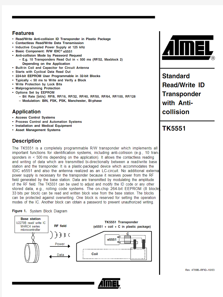
The TK5551 is a completely programmable R/W transponder which implements all important functions for identification systems, including anti-collision (e.g., 10 tran-sponders in < 500ms depending on the application). It allows the contactless reading and writing of data which are transmitted bi-directionally between a read/write base station and the transponder. It is a plastic-packaged device which accommodates the IDIC e5551 and also the antenna realized as an LC-circuit. No additional external power supply is necessary for the transponder because it receives power from the RF field generated by the base station. Data are transmitted by modulating the amplitude of the RF field. The TK5551 can be used to adjust and modify the ID code or any other stored data, e.g., rolling code systems. The on-chip 264-bit EEPROM (8 blocks,33bits per block) can be read and written block wise from the base station. The blocks can be protected against overwriting. One block is reserved for setting the operation modes of the IC. Another block can obtain a password to prevent unauthorized writing.Figure 1. System Block Diagram
2
TK5551
4709B–RFID–10/03
General
The transponder is the mobile part of the closed coupled identification system (see Fig-ure 1 on page 1), whereas the read/write base station is based on the U2270B or on discrete solutions, and the read/write transponder is based on the IDIC e5551.The transponder is a plastic cube device consisting of the following parts:?The transponder antenna, realized as a tuned LC circuit ?
Read/write IDIC (e5551) with EEPROM
Transponder Antenna
The antenna consists of a coil and a capacitor for tuning the circuit to the nominal carrier frequency of 125kHz. The coil has a ferrite core for improving the distance of read, write and programming operations.
Read/Write IDIC e5551
The read/write IDIC e5551 is part of the transponder TK5551. The data are transmitted bi-directionally between the base station and the transponder. The transponder receives power via a single coil from the RF signal generated by the base station. The single coil is connected to the chip and also serves as the IC’s bi-directional communication interface.
Data are transmitted by modulating the amplitude of the RF signal. Reading of register contents occurs by damping the coil by an internal load. Writing into registers occurs by interrupting the RF field in a specific way. The TK5551 transponder operates at a nomi-nal frequency of 125kHz. There are different bit rates and encoding schemes.
The on-chip 264-bit EEPROM (8 block, 33 bits each) can be read and written block wise from the base station. The blocks can be protected against overwriting by using lock bits. One block is reserved for setting the operation modes of the IC. Another block con-tains a password to prevent unauthorized writing.
See e5551 data sheet for more detailed information of the IDIC.Figure 2. Block Diagram of the e5551
3
TK5551
4709B–RFID–10/03
Absolute Maximum Ratings
Stresses beyond those listed under “Absolute Maximum Ratings” may cause permanent damage to the device. This is a stress rating only and functional operation of the device at these or any other conditions beyond those indicated in the operational sections of this specification is not implied. Exposure to absolute maximum rating conditions for extended periods may affect device reliability
Parameters
Symbol Value Unit Operating temperature range T amb -40 to +85°C Storage temperature range
T stg -40 to +125
°C Assembly temperature t < 5 minutes T ass 170°C Magnetic field strength at 125 kHz
H pp
1000
A/m
Operating Characteristics: Transponder
T amb = 25°C, f = 125 kHz, unless otherwise specified
Parameters Test Conditions Symbol
Min.Typ.Max.Unit Inductance
L
3.8
mH
LC Circuit, H pp = 20 A/m Resonance frequency Room temperature
f r 120
125130
kHz
Quality factor
Q LC
13
Magnetic Field Strength (H)Maximum field strength where tag does not modulate No influence to other tags in the field H pp not 4A/m Field strength for operation T amb = -40°C H pp -4030A/m T amb = 25°C H pp 2518A/m T amb = 85°C H pp 8517A/m Programming mode T amb = 25°C H pp 50
A/m Data retention EEPROM T amb = 25°C
t retention
10Y ears
Programming cycles EEPROM 100,000
Programming time/block RF = 125 kHz
t p 16
ms Maximum field strength
H pp max
600
A/m
Modulation Range (see also H-DV Curve )Modulation range
H pp = 20 A/m H pp = 30 A/m H pp = 50 A/m H pp = 100 A/m
DV
4.06.08.08.0
V
4
TK5551
4709B–RFID–10/03
Figure 3. Typical T K Range of Resonance Frequency
Figure 4. Typical H-DV Curve
Figure 5.
Measurement of the Modulation Range DV
5
TK5551
4709B–RFID–10/03
Measurement Assembly
All parameters are measured in a Helmholtz arrangement, which generates a homoge-nous magnetic field (see Figure 6 and Figure 7). A function generator drives the field generating coils, so the magnetic field can be varied in frequency and field strength.
Figure 6. Testing Application
Figure 7. Testing Geometry
6
TK5551
4709B–RFID–10/03
Writing Data into the TK5551
The write sequence of the TK5551 is shown below. Writing data into the transponder occurs by interrupting the RF field with short gaps. After the start gap the standard write OP code (10) is followed by the lock bit. The next 32bits contain the actual data. The last 3bits denote the destination block address. If the correct number of bits have been received, the actual data is programmed into the specified memory block.
Figure 8. Write Protocol
Write Data Decoding
The time elapsing between two detected gaps is used to encode the information. As soon as a gap is detected, a counter starts counting the number of field clock cycles until the next gap is detected. Depending on how many field clocks elapse, the data is regarded as '0' or '1'. The required number of field clocks is shown in Figure 9. A valid '0'is assumed if the number of counted clock periods is between 16 and 32, for a valid '1' it is 48 or 64 respectively. Any other value being detected results in an error, and the device exits write mode and returns to read mode.
Figure 9. Write Data Decoding Scheme
Actual Behavior of the Device
The TK5551 detects a gap if the voltage across the coils decreases below the threshold value of an internal MOS transistor. Until then, the clock pulses are counted. The num-ber given for a valid '0' or '1' (see Figure 9) refers to the actual clock pulses counted by the device. However, there are always more clock pulses being counted than were applied by the base station. The reason for this is the fact that an RF field cannot be switched off immediately. The coil voltage decreases exponentially. So although the RF field coming from the base station is switched off, it takes some time until the voltage across the coils reaches the threshold value of an internal MOS transistor and the device detects the gap.
Referring to the following diagram (see Figure 10 on page 7), this means that the device uses the times t 0 internal and t 1 internal . The exact times for t 0 and t 1 are dependent on the application (e.g., field strength, etc.)
Measured write-time frames of the IDIC demo kit software are:t 0 = 50 ms to 130 ms t 1 = 270 ms to 390 ms t gap = 180 ms to 400 ms
Antennas with a high Q-factor require longer times for t gap and shorter time values for t 0and t 1.
7
TK5551
4709B–RFID–10/03
Figure 10. Ideal and Real Behavior Signals
Operating Distance
The maximum distance between the base station and the TK5551 depends mainly on the base station, the coil geometries and the modulation options chosen (see “U2270B Antenna Design Hints” and the “U2270B” data sheet). Under laboratory conditions, a distance of up to 9cm can be reached. For optimized distance, please refer to the appli-cation note. When using Atmel’s U2270B demo board, the typical distances in the range of 0cm to 5cm can be achieved.
Anti-collision Mode by Password Request (AOR = Answer-On-Request)
The AOR mode is an anti-collision procedure for transponders to read, e.g., 10 tran-sponders in the field during 500ms (RF/32, maxblock 2). The number of transponders and the time to read out are dependent on the application.
If the AOR mode has been configured by AOR bit at block 0, the transponder remains in sleep mode while putting it into the field. If the specified AOR wake-up command is sent,the dedicated transponder generates an internal RESET (see section “OP Code For-mats” in the e5551 data sheet). Due to the RESET the transponder is woken up. That means, the transponder is able to modulate the field (read mode). The AOR wake-up command consists of the OP code and the 32-bit password. The time duration to send the AOR wake-up sequence is between 8.7ms and 27.5ms according to Figure 10.The time duration is dependent on the minimum/maximum values of the measured write-time frames and the content of the password. To select another transponder in the field, it is necessary to send the stop OP code to stop the modulation of the transponder.
8
TK5551
4709B–RFID–10/03
Application
Figure 11. Complete Transponder System with the Read/Write Base Station IC U2270B
9
TK5551
4709B–RFID–10/03
Ordering Information
Package Information
Extended Type Number Package Remarks
TK5551M-PP Plastic package
All kinds of modulation; RF/8, RF/16, RF/32, RF/40, RF/50,RF/64,RF/100 and RF/128(1)Default programmed: Manchester Modulation, RF/32, MAXBLK =2
Note:
1.
See data sheet e5551
Disclaimer: Atmel Corporation makes no warranty for the use of its products, other than those expressly contained in the Company’s standard warranty which is detailed in Atmel’s Terms and Conditions located on the Company’s web site. The Company assumes no responsibility for any errors which may appear in this document, reserves the right to change devices or specifications detailed herein at any time without notice, and does not make any commitment to update the information contained herein. No licenses to patents or other intellectual property of Atmel are granted by the Company in connection with the sale of Atmel products, expressly or by implication. Atmel’s products are not authorized for use as critical components in life support devices or systems.
Atmel Corporation
Atmel Operations
2325 Orchard Parkway San Jose, CA 95131, USA Tel: 1(408) 441-0311Fax: 1(408) 487-2600
Regional Headquarters
Europe
Atmel Sarl
Route des Arsenaux 41Case Postale 80CH-1705 Fribourg Switzerland
Tel: (41) 26-426-5555Fax: (41) 26-426-5500
Asia
Room 1219
Chinachem Golden Plaza 77 Mody Road Tsimshatsui East Kowloon Hong Kong
Tel: (852) 2721-9778Fax: (852) 2722-1369
Japan
9F, Tonetsu Shinkawa Bldg.1-24-8 Shinkawa
Chuo-ku, Tokyo 104-0033Japan
Tel: (81) 3-3523-3551Fax: (81) 3-3523-7581
Memory
2325 Orchard Parkway San Jose, CA 95131, USA Tel: 1(408) 441-0311Fax: 1(408) 436-4314
Microcontrollers
2325 Orchard Parkway San Jose, CA 95131, USA Tel: 1(408) 441-0311Fax: 1(408) 436-4314
La Chantrerie BP 70602
44306 Nantes Cedex 3, France Tel: (33) 2-40-18-18-18Fax: (33) 2-40-18-19-60
ASIC/ASSP/Smart Cards
Zone Industrielle
13106 Rousset Cedex, France Tel: (33) 4-42-53-60-00Fax: (33) 4-42-53-60-01
1150 East Cheyenne Mtn. Blvd.Colorado Springs, CO 80906, USA Tel: 1(719) 576-3300Fax: 1(719) 540-1759
Scottish Enterprise Technology Park Maxwell Building
East Kilbride G75 0QR, Scotland Tel: (44) 1355-803-000Fax: (44) 1355-242-743
RF/Automotive
Theresienstrasse 2Postfach 3535
74025 Heilbronn, Germany Tel: (49) 71-31-67-0
Fax: (49) 71-31-67-2340
1150 East Cheyenne Mtn. Blvd.Colorado Springs, CO 80906, USA Tel: 1(719) 576-3300Fax: 1(719) 540-1759
Biometrics/Imaging/Hi-Rel MPU/High Speed Converters/RF Datacom
Avenue de Rochepleine BP 123
38521 Saint-Egreve Cedex, France Tel: (33) 4-76-58-30-00Fax: (33) 4-76-58-34-80
Literature Requests
https://www.wendangku.net/doc/d816167624.html,/literature
4709B–RFID–10/03
? Atmel Corporation 2003. All rights reserved.
Atmel ? and combinations thereof are the registered trademarks of Atmel Corporation or its subsidiaries.Other terms and product names may be the trademarks of others.