K2CO3 catalysis on the reactivity of top charged coke and stamp charged coke
International Journal of Minerals , Metallurgy and Materials Volume 20, Number 1, January 2013, Page 17 DOI: 10.1007/s12613-013-0688-5
Corresponding author: Jian-liang Zhang E-mail: jl.zhang@https://www.wendangku.net/doc/d318446046.html,
? University of Science and Technology Beijing and Springer-Verlag Berlin Heidelberg 2013
K 2CO 3 catalysis on the reactivity of top charged coke and stamp charged coke
Qing-hai Pang, Jian-liang Zhang, Cheng-lin Qi, Chao Ma, De-wen Kong, and Rui Mao
School of Metallurgical and Ecological Engineering, University of Science and Technology Beijing, Beijing 100083, China (Received: 26 February 2012; revised: 30 March 2012; accepted: 17 April 2012)
Abstract: The catalysis of K 2CO 3 on the reactivity of top charged coke and stamp charged coke from Pansteel in China was studied. The coke reaction index of the stamp charged coke was 1%-2% higher than that of the top charged coke. Under the catalysis of K 2CO 3, the coke reaction index of both cokes approximately increased by 4%, 6%, 10% and 6% at 900, 1000, 1100 and 1200°C, respectively. The reactivity of the K-enriched stamp charged coke was 1%-2% higher than that of the K-enriched top charged coke below 1100°C. However, only negligible differences were found in the temperature zone between 1100 and 1200°C. Scanning electron microscopy images illustrated that pores in the top charged coke were smaller and equally distributed, while relatively more big pores exist non-homogenously in stamp charged coke. Due to the different processes in production, the stamp charged coke was more porous and most of the pores tended to be applanate. Cracks were observed in the microstructure of the stamp charged coke during the carbon solution reaction, implying the inferior quality of the stamp charged coke to the top charged coke at high temperature. Diffusion of K during the carbon solution reaction was studied by the energy dispersive spectrometry. It is found that K gradually spreads into the center of lumpy coke with the rising of temperature and is equally distributed on the edges of pores at 1200°C. Besides, oxidation reactions of functional groups become faster with the catalysis of K.content
Keywords: blast furnaces; coke; alkali metals; catalysis; reactivity
1. Introduction
Coke, as an essential raw material in blast furnace (BF) ironmaking, serves as a heat-generating agent, reducing agent, carburizing agent, and supporting spine of burden [1]. Pulverized coal (PC) injection may undertake partial functions of coke as a heat-genera-ting agent, reducing agent, and carburizing agent, by which the consumption of coke is reduced [2]. Conse-quently, the coke ratio is reduced and the coke load is increased, which makes the support of coke to loose burden more critical. Thus, high quality coke is re-quired at high temperature. According to previous in-vestigations [3-4], pores in coke are enlarged, walls between pores become thinner, and coke strength after reaction (CSR) decreases after the carbon solution re-action. The reactivity between coke and CO 2 at high temperatures over 1000°C is a key index, which is
widely adopted for evaluating the high temperature strength of coke [5].
Nowadays, many steel enterprises tend to produce stamp charged coke with weak coking coal instead of producing top charged coke with coking coal in con-sideration of the barren resources of coking coal and its disadvantage in price [3, 6-8]. Besides, there are abun-dant resources of weak coking coal in China whose price is much lower. Therefore, the utilization of stamp charged coke may effectively cut down the cost of the ironmaking process [9]. Meanwhile, the quality of stamp charged coke is almost the same as or slightly inferior to that of top charged coke [10]. With the de-velopment in production technology of stamp charged coke, there has been a significant enhancement in its yield and quality. Many steel enterprises attempt to partly or completely use stamp charged coke to reduce the cost. Taking into consideration that stamp charged
18 Int. J. Miner. Metall. Mater ., Vol. 20, No. 1, Jan. 2013
coke has been applied in smelting by Pansteel in China for years, even some furnaces are operated completely with stamp charged coke [11-12], the effects of the ca-talysis of K 2CO 3 on the coke reaction index (CRI) of top charged coke and stamp charged coke as well as coke structure were studied in this paper to provide theory basis for improvements in Pansteel ironmaking operation.
The contents of K and Na in coke are 0.05wt%- 0.3wt%, which mainly exist in the ash of coke and ac-counts for about 2wt% of the ash weight. With the consumption of coke, the content of alkali metals gradually increases. Meanwhile, the raw materials of ironmaking in Pansteel contain considerable contents of alkali metal elements. The catalysis of alkali metals accelerates the carbon solution reaction of coke and consequently deteriorates the CSR of coke. Due to the circulation and accumulation of alkali metals in the upper part of the BF shaft above the tuyeres, the con-
tents of K and Na sharply increase. The properties of coke at high temperature are seriously affected. Ac-cording to previous studies [13], alkali metals that catalyze the carbon solution reaction exist in the form of elementary substances or carbonates. K is the main element in the circulation of alkali metals in BF and simultaneously its content and catalysis are much higher than Na, which may severely deteriorate the strength of coke in the high temperature zones of BF [14].
2. Experimental
2.1. Sample
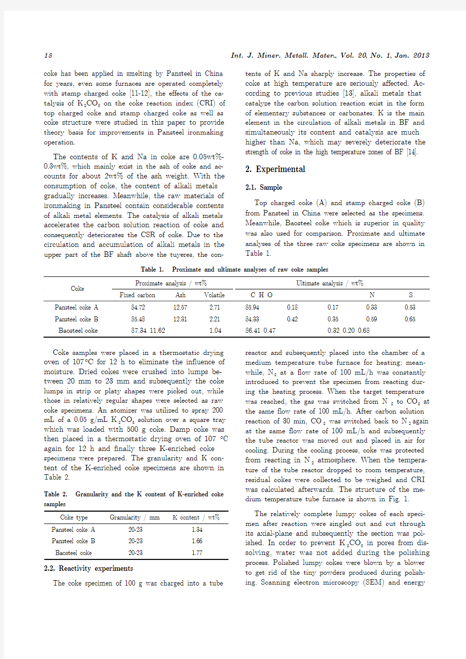
Top charged coke (A) and stamp charged coke (B) from Pansteel in China were selected as the specimens. Meanwhile, Baosteel coke which is superior in quality was also used for comparison. Proximate and ultimate analyses of the three raw coke specimens are shown in Table 1.
Table 1. Proximate and ultimate analyses of raw coke samples
Proximate analysis / wt% Ultimate analysis / wt%
Coke Fixed carbon
Ash Volatile C H O N S
Pansteel coke A 84.72 12.57 2.71 85.94 0.18 0.17 0.33 0.53 Pansteel coke B
85.48
12.31
2.21
84.33
0.42
0.35
0.59
0.65
Baosteel coke 87.34 11.62 1.04 86.41 0.47 0.32 0.20 0.68
Coke samples were placed in a thermostatic drying oven of 107°C for 12 h to eliminate the influence of moisture. Dried cokes were crushed into lumps be-tween 20 mm to 23 mm and subsequently the coke lumps in strip or platy shapes were picked out, while those in relatively regular shapes were selected as raw coke specimens. An atomizer was utilized to spray 200 mL of a 0.05 g/mL K 2CO 3 solution over a square tray which was loaded with 500 g coke. Damp coke was then placed in a thermostatic drying oven of 107°C again for 12 h and finally three K-enriched coke specimens were prepared. The granularity and K con-tent of the K-enriched coke specimens are shown in Table 2.
Table 2. Granularity and the K content of K-enriched coke samples
Coke type Granularity / mm
K content / wt%
Pansteel coke A 20-23 1.34 Pansteel coke B 20-23 1.66 Baosteel coke
20-23
1.77
2.2. Reactivity experiments
The coke specimen of 100 g was charged into a tube
reactor and subsequently placed into the chamber of a medium temperature tube furnace for heating; mean-while, N 2 at a flow rate of 100 mL/h was constantly introduced to prevent the specimen from reacting dur-ing the heating process. When the target temperature was reached, the gas was switched from N 2 to CO 2 at the same flow rate of 100 mL/h. After carbon solution reaction of 30 min, CO 2 was switched back to N 2 again at the same flow rate of 100 mL/h and subsequently the tube reactor was moved out and placed in air for cooling. During the cooling process, coke was protected from reacting in N 2 atmosphere. When the tempera-ture of the tube reactor dropped to room temperature, residual cokes were collected to be weighed and CRI was calculated afterwards. The structure of the me-dium temperature tube furnace is shown in Fig. 1. The relatively complete lumpy cokes of each speci-men after reaction were singled out and cut through its axial-plane and subsequently the section was pol-ished. In order to prevent K 2CO 3 in pores from dis-solving, water was not added during the polishing process. Polished lumpy cokes were blown by a blower to get rid of the tiny powders produced during polish-ing. Scanning electron microscopy (SEM) and energy
Q.H. Pang et al., K 2CO 3 catalysis on the reactivity of top charged coke and stamp charged coke
19
Fig. 1. Schematic illustration of apparatus for coke reactiv-ity measurement.
dispersive spectrometry (EDS) were utilized for the investigation of the microcosmic pore structure and the diffusion of K in coke during the carbon solution reaction under different conditions. 2.3. Functional group analysis
Variations in organic radicals in coke were deter-mined with the Fourier-transform infrared (FT-IR) system (VECTOR22) to investigate the influence of K 2CO 3 on functional groups in coke, which was oper-ated with a spectral resolution of 4 cm and in the range of 400-4000 cm ?1.
3. Results and discussion
3.1. Reactivity
The reactivity curves of different coke specimens in different reaction conditions are shown in Fig. 2. It can be observed that the CRI of raw coke A is about 1%-2% higher than that of raw coke B except for the case at 1100°C. Under the condition of adding K 2CO 3, the coke reactivity increases greatly in comparison with the raw coke. The CRI of K-enriched coke A at 900, 1000, 1100 and 1200°C increases by about 4%, 6%, 10% and 6%, respectively, while the same increments also occur to K-enriched coke B. Namely, the catalysis of K 2CO 3 is already very obvious since 900°C. With the rising of temperature, the catalysis of K is intensi-fied and reaches its maximum at 1100°C, where a maximum difference of 10% between the raw coke and K-enriched coke is noted. There is no significant dif-ference between the reactivity of K-enriched coke A and coke B. The difference of CRI around 900 and 1000°C is about 1%, whereas no difference can be found between the two coke specimens when the tem-perature reaches over 1100°
C.
Fig. 2. Reactivity of coke specimens.
Owing to the application of high grade coal as well as advanced technology in coal blending and coking, the reactivity of Baosteel raw coke is very stable in the temperature range of 1000 -1200°C with the variations about 1%. No significant difference can be found be-tween Baosteel raw coke and K-enriched coke. The re-activity difference between the two coke specimens is below 1% under 1100°C while the catalysis of K 2CO 3 becomes obvious when the temperature is over 1100°C. Nevertheless, there is only 2.5% reactivity variation at 1200°C, which suggests that Baosteel coke has a great resistance to the catalysis of K 2CO 3.
It can also be observed that reactivity of Pansteel raw coke is about 10% higher than that of Baosteel raw coke at 1200°C. This disparity is magnified to 15% after adding K 2CO 3, which indicates that the ca-talysis of K 2CO 3 is much stronger to Pansteel coke than that to Baosteel coke. The K 2CO 3 content in coke is relatively low in this research. However, circulation and accumulation in the softening zone and smelting zone and the dropping zone will make it sharply in-crease to 4%-7% [13]. Therefore, the catalysis of alkali metals to coke will be much stronger in actual BF production. 3.2. Microstructure
The external and internal structures of coke before and after reaction were observed by SEM for the in-vestigation of structural variations in two Pansteel coke specimens during reaction. Meanwhile, the struc-ture of Baosteel coke was also observed to study the difference in quality between Pansteel coke and Baos-teel coke.
3.2.1. External porosity
It is illustrated in Fig. 3 that the distribution of pores in coke A is more homogeneous than that in
20 Int. J. Miner. Metall. Mater ., Vol. 20, No. 1, Jan. 2013
coke B. Meanwhile, pores in coke A are smaller and spherical in shape, while that of coke B are relatively bigger and applanate in shape. The structure of Baos-teel coke is extremely different from that of Pansteel coke. Large areas of coke without pores are presented in Fig. 3(c). The number of pores in Baosteel coke is significantly less than that in the two coke specimens from Pansteel, even though large pores can also be found. The disparity in structure of coke from the two enterprises is possibly attributed to the differences in the selection of coal as well as the techniques in coal blending and coking processes, which result in the huge difference in coke quality.
A comparison between Fig. 3 and 4 shows that no obvious difference are observed between the unreacted and reacted raw coke, which suggests that the carbon solution reaction at 900°C for 30 min without catalysis just leads to subtle changes in the external structure of coke. Nevertheless, significant differences exist in the external structures of the reacted K-riched coke and the reacted raw coke. Strong catalysis of K 2CO 3 on the reactivity of the three coke specimens is noticed. As for the reacted raw coke, though pore walls at a certain depth become thinner and a small number of pores are connected, the edges and corners of pore walls are still remaining. However, in the condition of adding K 2CO 3, all edges and corners are passivated after reaction, si-multaneously the walls of pores are thinner and the extension of pore connections is deeper than those without K-enrichment. No great variation is found in the external structures of raw coke A and K-enriched
coke A after reaction though the carbon solution reac-
Fig. 3.
Structures of raw coke specimens before reaction: (a) coke A; (b) coke B; (c) Baosteel coke.
Fig. 4. External structures of coke specimens after reaction at 900°C: (a) raw coke A; (b) raw coke B; (c) Baosteel raw coke; (d) K-enriched coke A; (e) K-enriched coke B; (f) Baosteel K-enriched coke.
Q.H. Pang et al., K 2CO 3 catalysis on the reactivity of top charged coke and stamp charged coke
21
tion characteristic is deepened to some extent. The structure comparison of coke B before and after reac-tion shows that a faveolate structure is found in raw coke B; meanwhile, the edges and corners are very ob-vious. Nevertheless, obvious variations, i.e., all edges and corners disappear and simultaneously chambers are created by the connection of a large number of pores, are found in the external structure of K-enriched coke B after reaction.
Fig. 5 shows the morphology of six coke specimens reacted at 1200°C for 0.5 h. A comparison between Figs. 4 and 5 suggests that the carbon solution reac-
tion characteristic at 1200°C is more obvious than that at 900°C. Edges and corners in two Pansteel reacted raw coke specimens at 900°C completely eliminate at 1200°C; meanwhile, the diameters of pores in the ex-ternal coke structure are enlarged and the number of pores with diameters over 500 μm apparently increases. As for Baosteel coke, although the 30-min carbon solu-tion reaction was carried out at 1200°C, no obvious difference can be found between the unreacted coke and the reacted coke. Namely, Baosteel coke possesses a rather strong resistance to the catalysis of K 2CO 3
.
Fig. 5. External structures of coke specimens after reaction at 1200°C: (a) raw coke A; (b) raw coke B; (c) Baosteel raw coke; (d) K-enriched coke A; (e) K-enriched coke B; (f) Baosteel K-enriched coke.
Besides, the catalysis of K 2CO 3 at 1200°C seems to be much stronger. A comparison between reacted raw coke and reacted K-enriched coke shows that the thickness of pore walls in reacted K-enriched coke is much thinner than that of reacted raw coke. Edges and pores in reacted raw coke are smooth and regular, while plenty of sawteeth are found in pore edges in re-acted K-enriched coke. Therefore, it can be concluded that K 2CO 3 possesses a strong catalysis on the coke reactivity at high temperature. Great variations in structure are observed in reacted K-enriched coke B in comparison with unreacted raw coke, while those in reacted raw coke B are not obvious.
The phenomenon of carbon solution reaction is very
serious in reacted K-enriched coke B. Pore walls be-come much thinner after the corrosion of carbon solu-tion reaction. Baosteel coke, which possesses a rather low reactivity in previous reactions, is also seriously corroded by the K 2CO 3 catalyzed carbon solution reac-tion. Although structural variations can be hardly found in the samples reacted at 900, 1000 and 1100°C, substantially distinct changes are found in the struc-ture of Baosteel K-enriched coke after reacting at 1200°C. Pore walls become thinner and the edges of pores change from smooth surface to sawteeth, which manifests the strong catalysis of K 2CO 3. 3.2.2. Internal porosity
The internal structures of coke after reaction under 900°C for 30 min were investigated and the results are shown in Fig. 6. It shows that for the reacted raw coke the carbon solution reaction occurs mainly on the
22 Int. J. Miner. Metall. Mater ., Vol. 20, No. 1, Jan. 2013
Fig. 6. Internal structures of coke specimens after reaction at 900°C: (a) raw coke A; (b) raw coke B; (c) Baosteel raw coke; (d) K-enriched coke A; (e) K-enriched coke B; (f) Baosteel K-enriched coke.
external of the coke at low temperature. However, the quantity and diameter of pores are both increased in the internal structure of K-enriched coke, which proves the strong catalysis of K 2CO 3 on the interior of the coke.
Previous research indicated that the carbon solution
reaction mainly occurs on the surface of high reactivity coke [15]. This theory can be confirmed with the re-sults achieved without addition of K 2CO 3 in Fig. 7. It can be observed that no significant difference could be found in the coke specimens at 900 and 1200°C. How-
ever, the last three photos in Fig. 7 show that the in-
Fig. 7. Internal structures of coke specimens after reaction at 1200°C: (a) raw coke A; (b) raw coke B; (c) Baosteel raw coke; (d) K-enriched coke A; (e) K-enriched coke B; (f) Baosteel K-enriched coke.
Q.H. Pang et al., K 2CO 3 catalysis on the reactivity of top charged coke and stamp charged coke
23
teriors of all the three lumpy cokes are severely cor-roded under the catalysis of K 2CO 3. Pore walls are ob-viously thinner and simultaneously the number of big pores sharply increases, which indicates that the ca-talysis of K 2CO 3 is remarkably intensified at high temperature. It can be inferred that with the increas-ing of temperature, the catalysis of K 2CO 3 become stronger.
A great difference in reactivity between Baosteel coke and Pansteel coke is possible due to the porosity in coke structure, which determines the area of the carbon solution reaction interface and simultaneously the contact area between K and coke. Low porosity in Baosteel coke structure effectively restricts the carbon solution reaction and the diffusion of K. 3.2.3. Microstructure
The microstructures of different raw coke specimens
in Fig. 8 reveal various microporosities in the coke structures. Structures with basically huge pores and thick pore walls are observed in the reacted raw coke, but pore walls in reacted raw coke A is much thicker than those in reacted raw coke B. Furthermore, cracks are found on pore walls in reacted raw coke B, which are owing to the internal stress resulting from the thermal expansion. On the other hand, corrosion is observed in reacted coke samples in the condition of adding K. The quantity of tiny pores increases, which makes the walls between pores much thinner in com-parison to the reacted raw coke. In addition, cracks are also observed in two reacted K-enriched coke B speci-mens, while no apparent cracks in reacted K-enriched coke A can be found. It is considered that cracks ap-pearing during the carbon solution reaction are attrib-uted to the different production processes of coke,
which is not related to the addition of alkali metals.
Fig. 8. Optical microscope photos of coke specimens reacted at different temperatures in a certain depth: (a) reacted raw coke A, 1200°C; (b) reacted K-enriched coke A, 1200°C; (c) raw coke B, 1200°C; (d) K-enriched coke B, 1100°C; (e) K-enriched coke B, 1200°C.
3.3. Diffusion of K
In order to study the diffusion of K, coke B was se-lected to investigate the distribution of K in the unre-acted coke and its diffusion during the reaction. Semi-quantitative results were obtained by EDS, which may represent the K content in coke structures to some ex-tent.
The distribution of K in the exterior of unreacted coke A is described in Fig. 9. It is considered from the results that all K completely adheres to the surface of coke. Namely, emission of moisture during the drying process did not result in the spread of K into the inte-rior of coke.
Combining Fig. 10(b) and Fig. 10(c), it can be found that the content of K increases with the increa-sing of depth in a certain range from the exterior.
However, once this range is exceeded, the content of K
24 Int. J. Miner. Metall. Mater ., Vol. 20, No. 1, Jan. 2013
Fig. 9. Distribution of K in the unreacted coke: (a) SEM image; (b) spot scanning; (c) area scanning.
Fig. 10. Distribution of K in the exterior of the coke reacted at 900°C: (a) SEM image; (b) spot scanning; (c) line scanning spectra.
decreases with the increasing of depth. This pheno-menon suggests that certain quantity of K spreads into the deeper part of coke during the reaction at 900°C. Internal EDS analysis results of reacted K-enriched coke A at 900°C in Fig. 10 show that K tends to exist on the edges of pores. Simultaneously, K concentrates in the places where the ash content is high, which means that K is apt to exist in the ash produced by the carbon solution reaction and the surfaces of pores are the main reacting interfaces between CO 2 and coke. This phenomenon is also observed in EDS results in Figs. 11 and 12. Besides, area scanning results in Fig.
13 show that the distribution of K is homogenized when the temperature rises to 1200°C.
3.4. Structural influence on the carbon solution reac-tion
It is well known that the carbon solution reaction occurs on the interface between CO 2 and the coke ma-trix, which means that the carbon solution reaction rate in a porous coke structure is much faster than that in coke with a dense structure because of a larger specific area. The mechanism of the structural influ-ence on the carbon solution reaction is shown in Fig. 14. It is apparent that carbon solution reaction focuses
Fig. 11. Distribution of K in the interior of coke reacted at 900°C: (a) SEM image; (b) spot scanning.
Q.H. Pang et al., K 2CO 3 catalysis on the reactivity of top charged coke and stamp charged coke
25
Fig. 12.
Distribution of K in the exterior of coke reacted at 1200°C: (a) SEM image; (b) spot scanning.
Fig. 13.
Distribution of K in the interior of coke reacted at 1200°C: (a) SEM image; (b) spot scanning; (c) area scanning.
Fig. 14. Carbon solution reaction in different coke structures.
on the surface of dense coke particles, while corrosion can also take place in the interior of coke with open pores or cracks that supply a larger interfacial area. According to the above investigations, pores in coke B seem to be flat with thinner pore walls. Therefore, with the proceeding of the carbon solution reaction, pores in coke will be probably connected and open cracks which extend into the center of coke particles may be created. These open cracks will result in not only larger interfaces but also degradation in coke
quality, which collapses the supporting spine of bur-den.
3.5. Variation in functional groups in coke
In order to analyze the influence of K on functional groups in coke, functional groups in raw coke B and K-enriched coke B reacted at different temperatures were investigated. The results are shown in Fig. 15 and the characteristic peaks are numbered as 1 to 7 from the left to the right. The relationships between
26 Int. J. Miner. Metall. Mater., Vol. 20, No. 1, Jan. 2013
Fig. 15. FT-IR spectra of raw coke B (a) and K-enriched coke B (b).
the functional groups and the characteristic peaks are
summarized in Table 3.
Spectra of different reacted raw cokes are shown in
Fig. 15(a). It is illustrated that the oxidation rates of
hydroxyl, aromatic hydrocarbons, –CH
3
and –SH are
found to be faster at high temperature, which results
in the increases of oxygen functional groups, such as
–COOH and C–O. Besides, the significant increase in
ash is due to the high-speed carbon solution reaction
at high temperature.
Table 3. Classification of absorption peaks in FT-IR spectra
Peak No. Wavenumber /
cm?1
Functional group
3300 –OH
1
3030 –CH (aromatic ring) 2 2780-2350 –COOH
1610 Carbonyl substituted aromatic hydro-
carbon
1590-1470 Aromatic
hydrocarbon 3
1460 –CH
2
, –CH3, inorganic carbonate
4 137
5 –CH
3
1330-1110 C–O (phenol, alcohol, ether, ester)
5
1040-900 Ash
860 CH (1, 2, 4; 2, 4, 5; 1, 2, 3, 4, 5 substi-tuted aromatic hydrocarbon)
750 CH (1, 2 substituted aromatic
hydrocarbon)
6
700
CH (Single substituted or 1,3 substituted aromatic hydrocarbon)
7 550 –SH
Curves in Fig. 15(b) suggest that no notable differ-ence in radicals of hydroxyl and aromatic hydrocar-bons is discovered compared to the reacted raw coke, which indicates that no contribution has been made by K to the oxidation of these radicals. Nevertheless, it is interesting to note that variations in other characteris-tic peaks are of apparent differences. A good relation-ship can be observed between the variation in peak heights of 2, 4 to 7 and temperature, which implies that K may catalyze the substitution or oxidation re-action of these radicals. The height of No. 2 peak in the K-enriched coke increases with the increase in temperature and then stabilizes over 900°C, while the stabilization can be only achieved in the raw coke over 1100°C. It is likely that K may accelerate the forma-tion of –COOH; meanwhile, –COOH becomes stable over 1000°C with the assistance of K. A dramatic in-crease can be obtained in No. 5 peak, which suggests that a quicker reaction rate at high temperature leads to great increase in ash content. In addition, decreases in Nos. 4, 6 and 7 peaks resulting from K addition are much more significant than those of the raw coke. In other words, oxidation of high activity radicals is ac-celerated by the catalysis of K.
4. Conclusions
(1) Pores in the top charged coke seemed to be smaller than those in the stamp charged coke and the distribution of pores in the top charged coke was more homogeneous. In comparison, pores in the stamp charged coke were anomalous in shape and heteroge-neous in distribution. Simultaneously, cracks were produced in the stamp charged coke during the reac-tion, while cracks were not observed in the top charged coke.
(2) The effect of K catalysis was slightly stronger on
Q.H. Pang et al., K2CO3 catalysis on the reactivity of top charged coke and stamp charged coke 27
the stamp charged coke than on the top charged coke
because of its higher porosity. The reactivity of coke was slightly increased at low temperature as 900°C, whereas the catalysis was greatly intensified at high temperature as 1200°C. Not only the exterior but also the interior of coke was severely corroded.
(3) K tended to exist in the ash produced by the carbon solution reaction. Therefore, K was reserved in the reaction interface between coke and CO
2
which may continuously catalyze the coke reactivity.
(4) Significant variations in coke structure before and after reaction were observed, even though no ob-vious differences in reactivity were noticed between the top charged coke and the stamp charged coke. Pores in the stamp charged coke were much bigger and pore walls were much thinner, which probably indicated the weak strength of the stamp charged coke after the re-action. Thus, it can be concluded that CRI is not adequate for forecasting the coke quality at high tem-perature.
(5) With the proceeding of the carbon solution reac-tion, K gradually diffused into the interior of coke and eventually reached the center of lumpy coke. However, corrosion on the interior of coke was not as intense as that on the exterior because of the relatively lower
contents of K and CO
2
. Besides, the distribution of K was gradually homogenized with the increasing of temperature.
(6) Oxidation of hydrocarbon was accelerated by the catalysis of K.
Acknowledgements
This work was financially supported by the National Key Technologies R&D Program of China (No. 2011BAC01B02).
References
[1] M. Naito, S. Nomura, and K. Kato, Development of
production and utilization technology of coke with high
strength and high reactivity, Tetsu-To-Hagane, 96(2010),
No. 5, p. 201.
[2] S. Nomura and T.G. Callcott, Maximum rates of pul-
verized coal injection in ironmaking blast furnaces, ISIJ
Int., 51(2011), No. 7, p. 1033.
[3] H.M. Wang, C.L. Wang, X.H. Zhou, and Y. Wang, The
relation between metallurgical properties of coke and regular B.F. performance, Laigang Sci. Technol., 2009, No. 1, p. 64.
[4] S. Pusz, M. Krzesi ska,
ń?. Sm?dowski, J. Majewska, B.
Pilawaa, and B. Kwieci ska, Changes in a coke stru
ńc-ture due to reaction with carbon dioxide, Int. J. Coal Geol., 81(2010), No. 4, p. 287.
[5] M. Grigore, R. Sakurovs, D. French, and V. Sahajwalla,
Coke gasification: the influence and behavior of inherent catalytic mineral matter, Energy Fuels, 23(2009), No. 4, p. 2075.
[6] J.J. Xu, G. Liu, H.Y. Wei, and Y.L. Xu, The produc-
tion practice that use stamping coke to smelt at No. 4 BF in Hangang, Ironmaking Technol. Commun., 2009, No. 1, p. 3.
[7] S.H. Krishnan, R.S. Dash, M. Guha, D. Kumar, and
D.P. Deshpande, Application of binder in stamp charge
coke making, ISIJ Int., 44(2004), No. 7, p. 1150.
[8] P.S. Dash, S.H. Krishnan, R. Sharma, P.K. Banerjee,
and S.K. Haldar, Laboratory scale investigation to im-
prove the productivity of stamp charge coke oven through optimisation of bulk density of coal cake, ISIJ Int., 45(2005), No. 11, p. 1577
[9] X.S. Gao and A.M. Zhang, BF smelting with com-
pletely stamping coke, [in] Academic Annual Confer-
ence of Small and Middle Sized Blast Furnace, 2008, p.
473.
[10] P.K. Banerjee, S.H. Krishnan, and A.D. Baijal, Stamp
charged coke making technology, Trans. Indian Inst.
Met., 59(2006), No. 5, p. 535.
[11] J.L. Cao, The production practice that use stamping
coke to smelt at No. 2 BF in Pangang, Sichuan Metall., 32(2010), No. 6, p. 35.
[12] G. Wang and Y. Liu, The production practice that use
stamping coke to smelt at Pansteel BF, Sichuan Metall., 32(2010), No. 3, p. 28.
[13] Y.N. Fu, Blast Furnace Coke, Metallurgical Industry
Press, Beijing, 1995, p. 84.
[14] T. Hilding, S. Gupta, V. Sahajwalla, B. Bj?rkman, and
J. Wikstr?m, Degradation behaviour of a high CSR coke in an experimental blast furnace: effect of carbon structure and alkali reactions, ISIJ Int., 45(2005), No. 7, p. 1041.
[15] S. Nomura, M. Naito, and K. Yamaguchi, Post-reaction
strength of catalyst-added highly reactive coke, ISIJ Int., 47(2007), No. 6, p. 831.
黄自艺术歌曲钢琴伴奏及艺术成就
【摘要】黄自先生是我国杰出的音乐家,他以艺术歌曲的创作最为代表。而黄自先生特别强调了钢琴伴奏对于艺术歌曲组成的重要性。本文是以黄自先生创作的具有爱国主义和人道主义的艺术歌曲《天伦歌》为研究对象,通过对作品分析,归纳钢琴伴奏的弹奏方法与特点,并总结黄自先生的艺术成就与贡献。 【关键词】艺术歌曲;和声;伴奏织体;弹奏技巧 一、黄自艺术歌曲《天伦歌》的分析 (一)《天伦歌》的人文及创作背景。黄自的艺术歌曲《天伦歌》是一首具有教育意义和人道主义精神的作品。同时,它也具有民族性的特点。这首作品是根据联华公司的影片《天伦》而创作的主题曲,也是我国近代音乐史上第一首为电影谱写的艺术歌曲。作品创作于我国政治动荡、经济不稳定的30年代,这个时期,这种文化思潮冲击着我国各个领域,连音乐艺术领域也未幸免――以《毛毛雨》为代表的黄色歌曲流传广泛,对人民大众,尤其是青少年的不良影响极其深刻,黄自为此担忧,创作了大量艺术修养和文化水平较高的艺术歌曲。《天伦歌》就是在这样的历史背景下创作的,作品以孤儿失去亲人的苦痛为起点,发展到人民的发愤图强,最后升华到博爱、奋起的民族志向,对青少年的爱国主义教育有着重要的影响。 (二)《天伦歌》曲式与和声。《天伦歌》是并列三部曲式,为a+b+c,最后扩充并达到全曲的高潮。作品中引子和coda所使用的音乐材料相同,前后呼应,合头合尾。这首艺术歌曲结构规整,乐句进行的较为清晰,所使用的节拍韵律符合歌词的特点,如三连音紧密连接,为突出歌词中号召的力量等。 和声上,充分体现了中西方作曲技法融合的创作特性。使用了很多七和弦。其中,一部分是西方的和声,一部分是将我国传统的五声调式中的五个音纵向的结合,构成五声性和弦。与前两首作品相比,《天伦歌》的民族性因素增强,这也与它本身的歌词内容和要弘扬的爱国主义精神相对应。 (三)《天伦歌》的伴奏织体分析。《天伦歌》的前奏使用了a段进唱的旋律发展而来的,具有五声调性特点,增添了民族性的色彩。在作品的第10小节转调入近关系调,调性的转换使歌曲增添抒情的情绪。这时的伴奏加强和弦力度,采用切分节奏,节拍重音突出,与a段形成强弱的明显对比,突出悲壮情绪。 c段的伴奏采用进行曲的风格,右手以和弦为主,表现铿锵有力的进行。右手为上行进行,把全曲推向最高潮。左手仍以柱式和弦为主,保持节奏稳定。在作品的扩展乐段,左手的节拍低音上行与右手的八度和弦与音程对应,推动音乐朝向宏伟、壮丽的方向进行。coda 处,与引子材料相同,首尾呼应。 二、《天伦歌》实践研究 《天伦歌》是具有很强民族性因素的作品。所谓民族性,体现在所使用的五声性和声、传统歌词韵律以及歌曲段落发展等方面上。 作品的整个发展过程可以用伤感――悲壮――兴奋――宏达四个过程来表述。在钢琴伴奏弹奏的时候,要以演唱者的歌唱状态为中心,选择合适的伴奏音量、音色和音质来配合,做到对演唱者的演唱同步,并起到连接、补充、修饰等辅助作用。 作品分为三段,即a+b+c+扩充段落。第一段以五声音阶的进行为主,表现儿童失去父母的悲伤和痛苦,前奏进入时要弹奏的使用稍凄楚的音色,左手低音重复进行,在弹奏完第一个低音后,要迅速的找到下一个跨音区的音符;右手弹奏的要有棱角,在前奏结束的时候第四小节的t方向的延音处,要给演唱者留有准备。演唱者进入后,左手整体的踏板使用的要连贯。随着作品发展,伴奏与旋律声部出现轮唱的形式,要弹奏的流动性强,稍突出一些。后以mf力度出现的具有转调性质的琶音奏法,要弹奏的如流水般连贯。在重复段落,即“小
我国艺术歌曲钢琴伴奏-精
我国艺术歌曲钢琴伴奏-精 2020-12-12 【关键字】传统、作风、整体、现代、快速、统一、发展、建立、了解、研究、特点、突出、关键、内涵、情绪、力量、地位、需要、氛围、重点、需求、特色、作用、结构、关系、增强、塑造、借鉴、把握、形成、丰富、满足、帮助、发挥、提高、内心 【摘要】艺术歌曲中,伴奏、旋律、诗歌三者是不可分割的重 要因素,它们三个共同构成一个统一体,伴奏声部与声乐演唱处于 同样的重要地位。形成了人声与器乐的巧妙的结合,即钢琴和歌唱 的二重奏。钢琴部分的音乐使歌曲紧密的联系起来,组成形象变化 丰富而且不中断的套曲,把音乐表达的淋漓尽致。 【关键词】艺术歌曲;钢琴伴奏;中国艺术歌曲 艺术歌曲中,钢琴伴奏不是简单、辅助的衬托,而是根据音乐 作品的内容为表现音乐形象的需要来进行创作的重要部分。准确了 解钢琴伴奏与艺术歌曲之间的关系,深层次地了解其钢琴伴奏的风 格特点,能帮助我们更为准确地把握钢琴伴奏在艺术歌曲中的作用 和地位,从而在演奏实践中为歌曲的演唱起到更好的烘托作用。 一、中国艺术歌曲与钢琴伴奏 “中西结合”是中国艺术歌曲中钢琴伴奏的主要特征之一,作 曲家们将西洋作曲技法同中国的传统文化相结合,从开始的借鉴古 典乐派和浪漫主义时期的创作风格,到尝试接近民族乐派及印象主 义乐派的风格,在融入中国风格的钢琴伴奏写作,都是对中国艺术 歌曲中钢琴写作技法的进一步尝试和提高。也为后来的艺术歌曲写 作提供了更多宝贵的经验,在长期发展中,我国艺术歌曲的钢琴伴 奏也逐渐呈现出多姿多彩的音乐风格和特色。中国艺术歌曲的钢琴
写作中,不可忽略的是钢琴伴奏织体的作用,因此作曲家们通常都以丰富的伴奏织体来烘托歌曲的意境,铺垫音乐背景,增强音乐感染力。和声织体,复调织体都在许多作品中使用,较为常见的是综合织体。这些不同的伴奏织体的歌曲,极大限度的发挥了钢琴的艺术表现力,起到了渲染歌曲氛围,揭示内心情感,塑造歌曲背景的重要作用。钢琴伴奏成为整体乐思不可缺少的部分。优秀的钢琴伴奏织体,对发掘歌曲内涵,表现音乐形象,构架诗词与音乐之间的桥梁等方面具有很大的意义。在不断发展和探索中,也将许多伴奏织体使用得非常娴熟精确。 二、青主艺术歌曲《我住长江头》中钢琴伴奏的特点 《我住长江头》原词模仿民歌风格,抒写一个女子怀念其爱人的深情。青主以清新悠远的音乐体现了原词的意境,而又别有寄寓。歌调悠长,但有别于民间的山歌小曲;句尾经常出现下行或向上的拖腔,听起来更接近于吟哦古诗的意味,却又比吟诗更具激情。钢琴伴奏以江水般流动的音型贯穿全曲,衬托着气息宽广的歌唱,象征着绵绵不断的情思。由于运用了自然调式的旋律与和声,显得自由舒畅,富于浪漫气息,并具有民族风味。最有新意的是,歌曲突破了“卜算子”词牌双调上、下两阕一般应取平行反复结构的惯例,而把下阕单独反复了三次,并且一次比一次激动,最后在全曲的高音区以ff结束。这样的处理突出了思念之情的真切和执著,并具有单纯的情歌所没有的昂奋力量。这是因为作者当年是大革命的参加者,正被反动派通缉,才不得不以破格的音乐处理,假借古代的