nature上的一篇锂电文章—浓度梯度镍钴锰三元正极材料的制备与性能

High-energy cathode material for long-life and safe lithium batteries
Yang-Kook Sun 1*?,Seung-Taek Myung 2*,Byung-Chun Park 1,Jai Prakash 3,Ilias Belharouak 4and Khalil Amine 4?
Layered lithium nickel-rich oxides,Li [Ni 1?x M x ]O 2(M =metal),have attracted signi?cant interest as the cathode material for rechargeable lithium batteries owing to their high capacity,excellent rate capability and low cost 1–7.However,their low thermal-abuse tolerance and poor cycle life,especially at elevated temperature,prohibit their use in practical batteries 4–6.Here,we report on a concentration-gradient cathode material for rechargeable lithium batteries based on a layered lithium nickel cobalt manganese oxide.In this material,each particle has a central bulk that is rich in Ni and a Mn-rich outer layer with decreasing Ni concentration and increasing Mn and Co concentrations as the surface is approached.The former provides high capacity,whereas the latter improves the thermal stability.A half cell using our concentration-gradient cathode material achieved a high capacity of 209mA h g ?1and retained 96%of this capacity after 50charge–discharge cycles under an aggressive test pro?le (55?C between 3.0and 4.4V).Our concentration-gradient material also showed superior performance in thermal-abuse tests compared with the bulk composition Li [Ni 0.8Co 0.1Mn 0.1]O 2used as reference.These results suggest that our cathode material could enable production of batteries that meet the demanding performance and safety requirements of plug-in hybrid electric vehicles.
Recent severe fluctuations in crude-oil prices and global environmental concerns have accelerated efforts to develop lithium-ion batteries for plug-in hybrid electric vehicles (P-HEVs).One of the principal cathode materials for such lithium batteries,LiNi 0.80Co 0.15Al 0.05O 2,has been investigated intensely in the past ten years 1.However,Li [Ni 0.8Co 0.15Al 0.05]O 2shows poor thermal characteristics because of the oxygen release from the highly delithiated state (for example,Li 0.35–0.55[Ni 0.8Co 0.15Al 0.05]O 2),which oxidizes the electrolyte and leads to a severe thermal runaway of the cell 2–4.Furthermore,the high concentration of unstable Ni 4+,when charging this material,is reduced to a divalent and insulating NiO phase at the cathode surface,resulting in high interfacial cell impedance and poor cell electrochemical performance 4–6.Even though the Ni-rich material,Li [Ni 0.8Co 0.1Mn 0.1]O 2,has poor cycle life and safety issues,its high capacity of approximately 200mA h (g-oxide)?1remains attractive 7for high-energy batteries in the 40mile electric drive P-HEVs.For this application,5,000charge-depleting cycles and 15years of calendar life as well as excellent safety are of extreme importance 8.These challenging requirements make it difficult for conventional cathode materials to be adopted in P-HEVs.
1Center for Information and Communication Material,Department of Chemical Engineering,Hanyang University,Seoul 133-791,South Korea,2Department
of Chemical Engineering,Iwate University,4-3-5Ueda,Morioka,Iwate 020-8551,Japan,3Department of Chemical and Environmental Engineering,Illinois Institute of T echnology,10West 33rd Street,Chicago 60616,USA,4Electrochemical T echnology Program,Chemical Sciences and Engineering Division,Argonne National Laboratory,9700South Cass Avenue,Argonne,Illinois 60439,USA.*These authors contributed equally to this work.?e-mail:yksun@hanyang.ac.kr;amine@https://www.wendangku.net/doc/fc10043475.html,.
Interface
Bulk
Li(Ni 0.8 Co 0.1 Mn 0.1)O 2
(high capacity)
Surface
(high thermal stability)
Concentration-gradient
outer layer
Li(Ni 0.8?x Co 0.1+y Mn 0.1+z )O 2
0 ≤ x ≤ 0.340 ≤ y ≤ 0.130 ≤ z ≤ 0.21
Li(Ni 0.46 Co 0.23 Mn 0.31)O 2Figure 1|Schematic diagram of positive-electrode particle with Ni-rich core surrounded by concentration-gradient outer layer.A scanning electron micrograph of a typical particle is shown in Fig.2c.
Recently,we reported a core–shell-structured Li [(Ni 0.8Co 0.1Mn 0.1)0.8(Ni 0.5Mn 0.5)0.2]O 2(ref.9)material designed to improve the cycle life and safety of lithium batteries.The core material is Li [Ni 0.8Co 0.1Mn 0.1]O 2,which shows high capacity,whereas the shell consists of Li [Ni 0.5Mn 0.5]O 2,which provides structural and thermal stability in highly delithiated states 10–12.After carefully reviewing our analysis results,however,we found a structural mismatch between the core and the shell;voids of tens of nanometres between the core and the shell were found in the prepared core–shell powders after cycling 13,14.For example,a Ni-rich compound (core material)was believed to undergo a volume change of approximately 9–10%(ref.15),whereas the shell volume change was only 2–3%during de-intercalation of Li +ions 16.The different degrees of shrinkage within the same particle may lead to gradual separation of the core and shell,preventing the realization of high capacity,because the core part loses the pathway for the Li +ions and the electron transfer provided by the shell.This discontinuity results in a drastic decline of battery performance.
Here,we report on a novel high-capacity and safe cathode material with an average composition of Li [Ni 0.68Co 0.18Mn 0.18]O 2,in which each particle consists of bulk material surrounded by a concentration-gradient outer layer.As illustrated in Fig.1,the bulk is a nickel-rich layered oxide (Li [Ni 0.8Co 0.1Mn 0.1]O 2)to satisfy the high energy and power requirement for the P-HEVs.In the outer layer,the reactive nickel ions are gradually replaced with
320
NATURE MATERIALS |VOL 8|APRIL 2009|https://www.wendangku.net/doc/fc10043475.html,/naturematerials
Outer layer
Distance (μm)
Distance (μm)
I n t e n s i t y (c o u n t )
b
a
c Hydroxide
Oxide
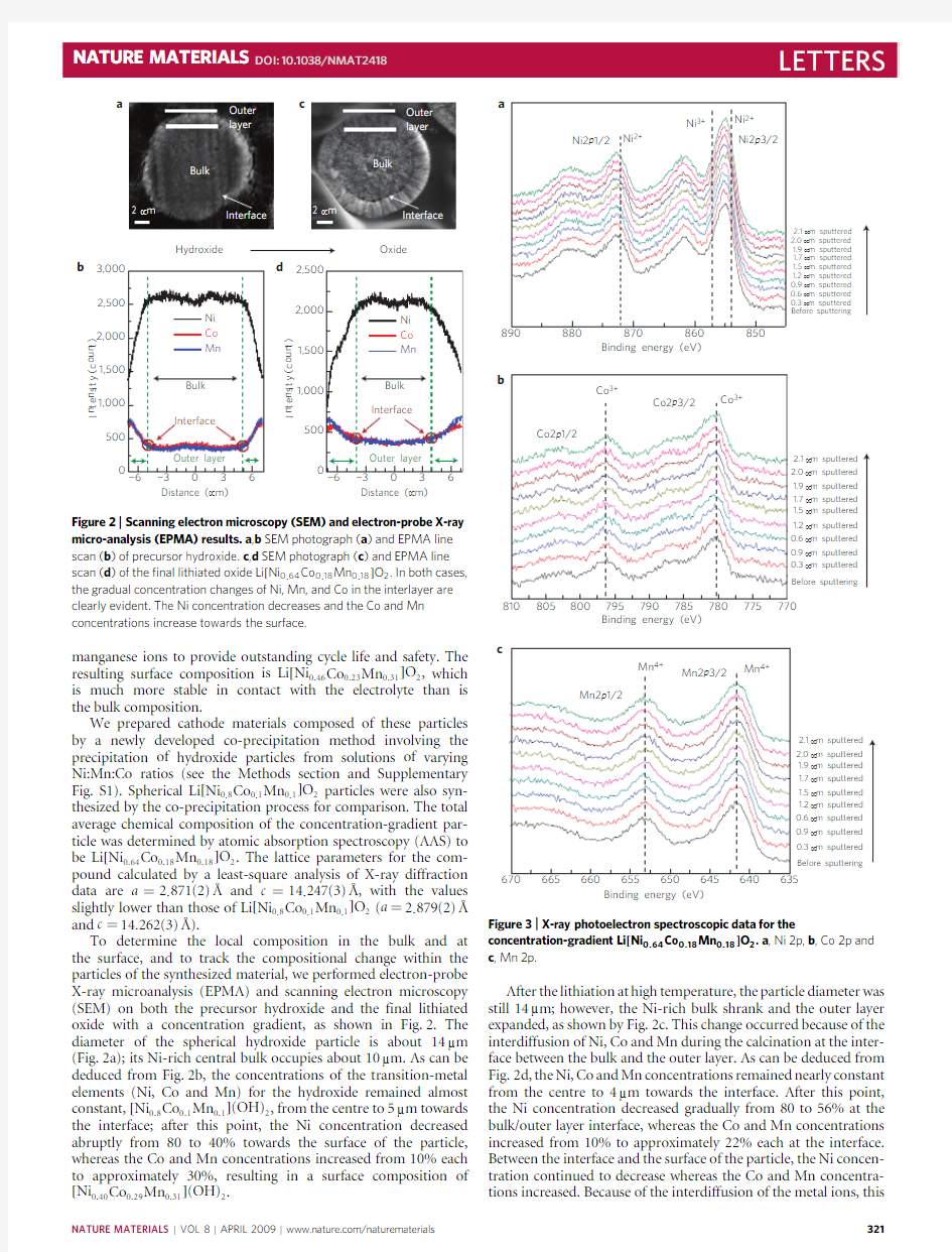
Figure 2|Scanning electron microscopy (SEM)and electron-probe X-ray micro-analysis (EPMA)results.a ,b SEM photograph (a )and EPMA line scan (b )of precursor hydroxide.c ,d SEM photograph (c )and EPMA line scan (d )of the ?nal lithiated oxide Li [Ni 0.64Co 0.18Mn 0.18]O 2.In both cases,the gradual concentration changes of Ni,Mn,and Co in the interlayer are clearly evident.The Ni concentration decreases and the Co and Mn concentrations increase towards the surface.
manganese ions to provide outstanding cycle life and safety.The resulting surface composition is Li [Ni 0.46Co 0.23Mn 0.31]O 2,which is much more stable in contact with the electrolyte than is the bulk composition.
We prepared cathode materials composed of these particles by a newly developed co-precipitation method involving the precipitation of hydroxide particles from solutions of varying Ni:Mn:Co ratios (see the Methods section and Supplementary Fig.S1).Spherical Li [Ni 0.8Co 0.1Mn 0.1]O 2particles were also syn-thesized by the co-precipitation process for comparison.The total average chemical composition of the concentration-gradient par-ticle was determined by atomic absorption spectroscopy (AAS)to be Li [Ni 0.64Co 0.18Mn 0.18]O 2.The lattice parameters for the com-pound calculated by a least-square analysis of X-ray diffraction data are a =2.871(2)?and c =14.247(3)?,with the values slightly lower than those of Li [Ni 0.8Co 0.1Mn 0.1]O 2(a =2.879(2)?and c =14.262(3)?).
To determine the local composition in the bulk and at the surface,and to track the compositional change within the particles of the synthesized material,we performed electron-probe X-ray microanalysis (EPMA)and scanning electron microscopy (SEM)on both the precursor hydroxide and the final lithiated oxide with a concentration gradient,as shown in Fig.2.The diameter of the spherical hydroxide particle is about 14μm (Fig.2a);its Ni-rich central bulk occupies about 10μm.As can be deduced from Fig.2b,the concentrations of the transition-metal elements (Ni,Co and Mn)for the hydroxide remained almost constant,[Ni 0.8Co 0.1Mn 0.1](OH)2,from the centre to 5μm towards the interface;after this point,the Ni concentration decreased abruptly from 80to 40%towards the surface of the particle,whereas the Co and Mn concentrations increased from 10%each to approximately 30%,resulting in a surface composition of [Ni 0.40Co 0.29Mn 0.31](OH)2
.
Binding energy (eV)
Binding energy (eV)
2.1 μm sputtered μm sputtered 1.9 μm sputtered 1.7 μm sputtered 1.5 μm sputtered 1.2 μm sputtered μm sputtered μm sputtered μm sputtered Before sputtering
2.1 μm sputtered 2.0 μm sputtered 1.9 μm sputtered 1.7 μm sputtered 1.5 μm sputtered 1.2 μm sputtered 0.6 μm sputtered 0.9 μm sputtered 0.3 μm sputtered 2.1 μm sputtered μm sputtered 1.9 μm sputtered 1.7 μm sputtered 1.5 μm sputtered 1.2 μm sputtered μm sputtered μm sputtered μm sputtered c
Figure 3|X-ray photoelectron spectroscopic data for the
concentration-gradient Li [Ni 0.64Co 0.18Mn 0.18]O 2.a ,Ni 2p,b ,Co 2p and c ,Mn 2p.
After the lithiation at high temperature,the particle diameter was still 14μm;however,the Ni-rich bulk shrank and the outer layer expanded,as shown by Fig.2c.This change occurred because of the interdiffusion of Ni,Co and Mn during the calcination at the inter-face between the bulk and the outer layer.As can be deduced from Fig.2d,the Ni,Co and Mn concentrations remained nearly constant from the centre to 4μm towards the interface.After this point,the Ni concentration decreased gradually from 80to 56%at the bulk/outer layer interface,whereas the Co and Mn concentrations increased from 10%to approximately 22%each at the interface.Between the interface and the surface of the particle,the Ni concen-tration continued to decrease whereas the Co and Mn concentra-tions increased.Because of the interdiffusion of the metal ions,this
NATURE MATERIALS |VOL 8|APRIL 2009|https://www.wendangku.net/doc/fc10043475.html,/naturematerials
321
Capacity (mA h g ?1)
V o l t a g e (V )
Cycling number
Cycling number
C a p a c i t y (m A h g ?1)
D i s c h a r g e c a p a c i t y (m A h g ?1)
160
180
200
220a
b
c
Figure 4|Charge–discharge characteristics of Li [Ni 0.8Co 0.1Mn 0.1]O 2,Li [Ni 0.46Co 0.23Mn 0.31]O 2and concentration-gradient
Li [Ni 0.64Co 0.18Mn 0.18]O 2.a ,Initial charge and discharge curves of Li [Ni 0.8Co 0.1Mn 0.1]O 2and concentration-gradient material at 55?C obtained from a 2032coin-type half cell using Li metal as the anode (current density:0.5-C rate corresponds to 95mA g ?1);b ,cycling performance of half cells based on Li [Ni 0.8Co 0.1Mn 0.1]O 2,Li [Ni 0.46Co 0.23Mn 0.31]O 2and concentration-gradient material cycled between 3.0and 4.4V at 55?C by applying a constant current of 0.5-C rate (95mA g ?1);c ,cycling performance at 1-C rate (75mA corresponds to 190mA g ?1)of laminated-type lithium-ion batteries with an Al-pouch full cell (75mA h)using mesocarbon microbead graphite as the anode and either Li [Ni 0.8Co 0.1Mn 0.1]O 2or concentration-gradient material as the cathode (upper cut-off voltage of 4.2V).
concentration change is less steep than in the case of the precursor hydroxide (compare Fig.2b,d).The composition at the surface of the particles seemed to be Li [Ni 0.46Co 0.23Mn 0.31]O 2according to the EPMA.As per our design,the intentionally induced Ni,Co and Mn concentration difference in the hydroxide precursor resulted in a final lithiated oxide with a concentration gradient that started at the interface and continued towards the surface of the particle.
X-ray photoelectron spectroscopy measurements were made to investigate the oxidation state of each transition-metal element for the concentration-gradient cathode particles.As shown in Fig.3a,the oxidation state of Ni near the surface is slightly higher than 2+.The observed binding energies for Co and Mn coincide well with those for Co 3+and Mn 4+,respectively,in Fig.3b,c.These results are in agreement with our previous X-ray absorption spectroscopy results for Li [Ni 0.4Co 0.3Mn 0.3]O 2(ref.17);the average oxidation states of Co and Mn for Li [Ni 0.4Co 0.3Mn 0.3]O 2were 3+and 4+,respectively,and that of Ni was slightly higher than 2+.Further sputtering of the surfaces of our material did not change the binding energies for Ni,Co and Mn,as shown in Fig.3.Even though the concentration-gradient particles were etched by up to 2.1μm in depth,which corresponds to the interface region,there were no apparent changes in the binding energies for Ni,Co and Mn.The composition in the bulk of the particle was Li [Ni 0.8Co 0.1Mn 0.1]O 2,and the oxidation state of each Ni,Co and Mn ion,thus,would be preferentially trivalent 17,18.However,some of the manganese near the interface may be tetravalent.Therefore,in the final lithiated oxide material,both the concentration and the oxidation state of Ni,Co and Mn change from the bulk to the surface of the particle.
We characterized the battery performance by comparison of the Li [Ni 0.8Co 0.1Mn 0.1]O 2and the concentration-gradient cathode materials.As seen in Fig.4a,the Li [Ni 0.8Co 0.1Mn 0.1]O 2material de-livered a discharge capacity of approximately 212mA h /(g oxide).A slight decrease in capacity (209mA h g ?1)was observed for the concentration-gradient material.To assess the stability of our new material,we selected an aggressive test profile where the cells were charged up to 4.4V and cycled at 55?C (Fig.4b).Cells based on both Li [Ni 0.8Co 0.1Mn 0.1]O 2and our concentration-gradient mate-rial show a high initial capacity of approximately 209mA h g ?1,which could meet the energy requirement needed for P-HEVs.However,the cell based on the bulk Li [Ni 0.8Co 0.1Mn 0.1]O 2com-position retained only 67%of its initial capacity after 50cycles,whereas our material showed excellent capacity retention of 96%during the same cycling period,which is similar to the cell based on the surface composition only,Li [Ni 0.46Co 0.23Mn 0.31]O 2.This result clearly indicates that our cathode material can provide
high
T emperature (°C)
H e a t f l o w (W g ?1)
Figure 5|Differential scanning calorimetry traces showing heat ?ow from the reaction of the electrolyte with Li 1?δ[Ni 0.8Co 0.1Mn 0.1]O 2,concentration-gradient material Li 1?σ[Ni 0.64Co 0.18Mn 0.18]O 2and Li 1?σ[Ni 0.46Co 0.28Mn 0.31]O 2charged to 4.3V.
capacity with long cycle and calendar life even at high temperature and high cut-off voltage.
Figure 4c shows the capacity retention of the Li [Ni 0.8Co 0.1Mn 0.1]O 2and our concentration-gradient material using an Al-pouch full cell with graphite as the anode.Although the cell based on Li [Ni 0.8Co 0.1Mn 0.1]O 2retained only 80.4%of its initial value after 500cycles,our concentration-gradient material showed much higher capacity retention of over 96.5%.The poor cycling performance of Li [Ni 0.8Co 0.1Mn 0.1]O 2could originate from a structural transformation at the particle surface because of the high reactivity of the Ni ions with the electrolyte,which,in turn,could increase the charge-transfer resistance between the cathode and the electrolyte on cycling 5,19–22.By reducing the Ni concentration and increasing the Mn concentration in the outer layer,we were able to stabilize the near-surface region of the material and thus limit its reactivity with the electrolyte.Also,the concentration gradient within the particle prevents the formation of microcracks and the segregation that can occur at the interface between the bulk and the outer layer,especially if there is a sharp variation of the composition at this point.
The thermal stability and safety of cathode material during charging are important concerns in judging the suitability of the material for use in lithium ion batteries for practical
322
NATURE MATERIALS |VOL 8|APRIL 2009|https://www.wendangku.net/doc/fc10043475.html,/naturematerials
applications such as P-HEVs.Figure5shows the differential scanning calorimetry profiles of Li1?δ[Ni0.8Co0.1Mn0.1]O2and our concentration-gradient material charged to4.3V in the presence of1M LiPF6/ethylene carbonate–diethyl carbonate electrolyte.For Li1?δ[Ni0.8Co0.1Mn0.1]O2,the onset temperature of the exothermic reaction occurred at approximately180?C,with a peak at220?C. The reduced content of Ni in layer LiMNiO2(M=Co,Mn)gives rise to reduced heat generation,but,significantly,does not improve the thermal stability23.However,our concentration-gradient material shows higher onset temperature and reduced heat generation compared with the bulk composition Li[Ni0.8Co0.1Mn0.1]O2.We propose that the stability of this material originates from the Mn4+in the surface region.For example,the onset temperature of the exothermic reaction was270?C for the concentration-gradient Li[Ni0.64Co0.18Mn0.18]O2;thus,the reaction with the electrolyte was delayed by approximately90?C compared with Li1?δ[Ni0.8Co0.1Mn0.1]O2,owing to the high stability of the outer surface composition Li[Ni0.46Co0.23Mn0.31]O2in our concentration-gradient material,which shows an onset temperature of over305?C. The total generated heat was2,303J g?1with our material,which is31%lower than that determined for Li1?δ[Ni0.8Co0.1Mn0.1]O2 (3,346J g?1).Those results were corroborated by nail penetration test (see Supplementary Fig.S4).The cell based on Li[Ni0.8Co0.1Mn0.1]O2 shows a major thermal runaway with explosion and fire;however, the cell using the concentration-gradient Li[Ni0.64Co0.18Mn0.18]O2 shows no thermal event.
The oxidation state of Ni for Li[Ni0.8Co0.1Mn0.1]O2is3and may reach3.7or3.8in a highly delithiated state,which can result in high reactivity with the electrolyte.Meanwhile,the concentration-gradient Li[Ni0.64Co0.18Mn0.18]O2has low nickel content at the surface,and the amount of Ni4+that is formed after charging should be lower than in Li[Ni0.8Co0.1Mn0.1]O2.In addition,even though the same capacity is delivered,the resulting oxidation state for the Ni would be slightly lower owing to the two-electron reaction of Ni(Ni2++2e?→Ni4+)of the composition for the outer layer.
A combined effect such as the presence of more stable Ni2+and the low concentration of Ni at the surface contributes to the thermal stability of our material.Furthermore,the surface consists of Li[Ni0.46Co0.23Mn0.31]O2,which is rich in tetravalent Mn,which leads to stable thermal behaviour in highly delithiated states.
In conclusion,we have developed a cathode material that has a concentration-gradient structure within each particle’s outer layer.This material shows not only a very high reversible capacity of209mA h g?1based on the particle bulk composition of Li[Ni0.8Co0.1Mn0.1]O2,but also excellent cycling and safety characteristics,which are attributed to the stability of the concentration-gradient outer layer and the surface composition of Li[Ni0.46Co0.23Mn0.31]O2.This material should eventually lead to advanced lithium-ion batteries that meet the P-HEV requirements. We anticipate that this novel approach should lead to the design and development of a wide range of other safe and stable,high-capacity intercalation compounds.
Methods
Synthesis of Li[Ni0.8Co0.1Mn0.1]O2.To synthesize spherical Li[Ni0.8Co0.1Mn0.1]O2, we used NiSO4·6H2O,CoSO4·7H2O and MnSO4·5H2O(8:1:1in molar ratio)as starting materials for the co-precipitation.Details of the preparation procedures are described in a previous report22.The as-co-precipitated particles were filtered and washed with deionized water.The obtained powders were dried in a vacuum state at25?C to remove adsorbed water.Finally,a mixture of LiNO3and the produced hydroxide(Li/Ni+Co+Mn ratio=1)was calcined at750?C for20h in air.Then, it was cooled to room temperature in the furnace.
Synthesis of concentration-gradient material.To prepare the concentration-gradient cathode material,we also used NiSO4·6H2O,
CoSO4·7H2O and MnSO4·5H2O(8:1:1in molar ratio)as starting materials
for the co-precipitation of[Ni0.8Co0.1Mn0.1](OH)2.During the reaction,Ni-poor aqueous solution(Ni:Co:Mn=0.08:0.46:0.46in molar ratio)was pumped into a Ni-rich(Ni:Co:Mn=0.8:0.1:0.1in molar ratio)solution tank,after which the homogeneously mixed solution was fed into a continuously stirred tank reactor. The obtained particles were filtered,washed with deionized water and dried at25?C to remove adsorbed water in a vacuum state.Finally,a mixture of the produced hydroxide and LiNO3(Li/Ni+Co+Mn ratio=1)was calcined at780?C for20h in air.Then,it was cooled to room temperature in a furnace.
Materials characterization.The crystalline phase of the prepared powders was identified at each stage by powder X-ray diffraction(Rigaku,Rint-2000)using Cu Kαradiation.The diffraction data were obtained at2θ=10?–110?,with a step size of0.03?.The morphology of the prepared powders was also observed by scanning electron microscopy(JSM-6340F,JEOL).Line scans of the polished surfaces for the prepared concentration-gradient hydroxide and calcined lithiated powders were analysed by an electron-probe microanalyser(JXA-8100,JEOL). Chemical compositions were analysed by atomic absorption spectroscopy(Vario 6,Analyticjena).X-ray photoelectron spectroscopy(PHI5600,Perkin Elmer) measurements were made to investigate the electronic state of Ni,Co and Mn for the concentration-gradient material.Macromode(about3mm×3mm)Ar-ion etching was used to determine the concentration depth profiles of the powders. The etching rate was estimated as4.2nm min?1.
Electrochemical test.For fabrication of the positive electrodes,the prepared powders were mixed with carbon black and polyvinylidene fluoride(80:10:10)
in N-methylpyrrolidinon.The obtained slurry was coated onto Al foil and
roll-pressed.The electrodes were dried overnight at120?C in a vacuum before use. Preliminary cell tests were done with a2032coin-type cell using Li metal as the anode.The cycle-life tests were performed in a laminated-type full cell wrapped with an Al pouch(thickness,1mm;width,40mm;length,60mm;capacity,
75mA h).Mesocarbon microbead graphite(Osaka Gas)was used as the anode.The electrolyte solution was1M LiPF6in ethylene carbonate–diethyl carbonate(1:1in volume).The cell was cycled between3and4.2V at a very low rate of0.01–0.5C (1.9–95mA g?1)during the initial formation process.The cells were charged and discharged between3.0and4.2V by applying a constant1-C current(75mA corresponds to190mA g?1)at25?C.
Thermal properties For the differential scanning calorimetry experiments,
the cells were charged to4.3V versus Li and disassembled in an Ar-filled dry box.A stainless-steel sealed pan with a gold-plated copper seal(which can withstand150atm of pressure before rupturing and has a capacity of30μl) was used to collect3–5mg samples.The measurements were carried out in a Pyris1differential scanning calorimeter(Perkin Elmer)using a temperature scan rate of1?C min?1.The weight was constant in all cases,indicating no leaks during the experiments.
For the nail penetration test,Li-ion batteries(thickness,1.5mm;width,
40mm;length,60mm;capacity,120mA h)charged to4.2V were penetrated by a sharp stainless-steel nail at a constant speed of4mm s?1controlled by a motor.The cell temperature and cell voltage were monitored during the test.
Received2June2008;accepted18February2009; published online22March2009
References
1.Kostecki,R.&McLarnon,F.Local-probe studies of degradation of
composite LiNi0.8Co0.15Al0.05O2cathodes in high-power lithium-ion cells.
Electrochem.Solid State Lett.7,A380–A383(2004).
2.Dahn,J.R.,Fuller,E.W.,Obrovac,M.&Sacken,U.von.Thermal stability of
Li x CoO2,Li x NiO2and l-MnO2and consequences for the safety of Li-ion cells.
Solid State Ionics69,265–270(1994).
3.Arai,H.et al.Electrochemical and thermal behavior of LiNi1?z M z O2(M=Co,
Mn,Ti).J.Electrochem.Soc.144,3117–3125(1997).
4.Shim,J.et al.Electrochemical analysis for cycle performance and capacity
fading of a lithium-ion battery cycled at elevated temperature.J.Power Sources 112,222–230(2002).
5.Wright,R.B.et al.Power fade and capacity fade resulting from cycle-life
testing of advanced technology development program lithium-ion batteries.
J.Power Sources112,865–869(2003).
6.Belharouak,I.,Lu,W.,Vissers,D.&Amine,K.Safety characteristics of
Li(Ni0.8Co0.15Al0.05)O2and Li(Ni1/3Co1/3Mn1/3)https://www.wendangku.net/doc/fc10043475.html,mun.8, 329–335(2006).
7.Kim,M.-H.,Shin,H.-S.,Shin,D.&Sun,Y.-K.Synthesis and electrochemical
properties of Li[Ni0.8Co0.1Mn0.1]O2and Li[Ni0.8Co0.2]O2via co-precipitation.
J.Power Sources159,1328–1333(2006).
8.FreedomCAR PHEV battery test manual,
9.Sun,Y.-K.et al.Synthesis and characterization of
Li[(Ni0.8Co0.1Mn0.1)0.8–(Ni0.5Mn0.5)0.2]O2with the microscale core–shell
structure as the positive electrode material for lithium batteries.
J.Am.Chem.Soc.127,13411–13418(2005).
10.Ohzuku,T.&Makimura,https://www.wendangku.net/doc/fc10043475.html,yered lithium insertion material of
LiNi1/2Mn1/2O2:A possible alternative to LiCoO2for advanced lithium-ion batteries.Chem.Lett.30,744–745(2001).
NATURE MATERIALS|VOL8|APRIL2009|https://www.wendangku.net/doc/fc10043475.html,/naturematerials323
11.Lu,Z.,MacNeil,D.D.&Dahn,https://www.wendangku.net/doc/fc10043475.html,yered cathode materials
Li[Ni x Li(1/3?2x/3)Mn(2/3?x/3)]O2for lithium-ion batteries.
Electrochem.Solid-State Lett.4,A191–A194(2001).
12.Kim,J.-S.,Johnson,C.S.&Thackeray,https://www.wendangku.net/doc/fc10043475.html,yered x LiMO2·(1?x)Li2M O3
electrodes for lithium batteries:A study of0.95LiMn0.5Ni0.5O2·0.05Li2TiO3.
https://www.wendangku.net/doc/fc10043475.html,mun.4,205–209(2002).
13.Sun,Y.-K.,Myung,S.-T.,Park,B.-C.&Amine,K.Synthesis
of spherical nano-to microscale core–shell particles
Li[(Ni0.8Co0.1Mn0.1)1?x(Ni0.5Mn0.5)x]O2and their applications to lithium
batteries.Chem.Mater.18,5199–5163(2006).
14.Sun,Y.K.et al.Novel core–shell-structured Li[(Ni0.8Co0.2)0.8(Ni0.5Mn0.5)0.2]O2
via coprecipitation as positive electrode material for lithium secondary
batteries.J.Phys.Chem.B110,6810–6815(2006).
15.Koyama,Y.et al.Crystal and electronic structures of superstructural
Li1?x[Co1/3Ni1/3Mn1/3]O2(0≤x≤1).J.Power Sources119-121,
644–648(2003).
16.Myung,S.-T.et al.Synthesis of Li[(Ni0.5Mn0.5)1?x Li x]O2by emulsion drying
method and impact of excess Li on structural and electrochemical properties.
Chem.Mater.18,1658–1666(2006).
17.Lee,K.-S.et al.Structural and electrochemical properties of layered
Li[Ni1?2x Co x Mn x]O2(x=0.1–0.3)positive electrode materials for Li-ion
batteries.J.Electrochem.Soc.154,A971–A977(2007).
18.Cho,J.et al.Storage characteristics of LiNi0.8Co0.1+x Mn0.1?x O2(x=0,0.03,
and0.06)cathode materials for lithium batteries.J.Electrochem.Soc155,
A239–A245(2008).19.Abraham,D.P.et al.Microscopy and spectroscopy of lithium nickel
oxide-based particles used in high power lithium-ion cells.J.Electrochem.Soc.
150,A1450–A1456(2003).
20.Striebel,K.A.et al.Diagnostic analysis of electrodes from high-power
lithium-ion cells cycled under different conditions.J.Electrochem.Soc.151, A857–A866(2004).
21.Woo,S.-U.Improvement of electrochemical performances of
Li[Ni0.8Co0.1Mn0.1]O2cathode materials by fluorine substitution.
J.Electrochem.Soc.154,A649–A655(2007).
22.Lee,M.-H.,Kang,Y.-J.,Myung,S.-T.&Sun,Y.-K.Synthetic optimization
of Li[Ni1/3Co1/3Mn1/3]O2via co-precipitation.Electrochim.Acta50,
939–948(2004).
23.Dahn,J.R.et al.A comparison of the electrode/electrolyte reaction at elevated
temperatures for various Li-ion battery cathodes.J.Power Sources108,
8–14(2002).
Acknowledgements
This work was supported by the Global Research Network Program in collaboration with the US Department of Energy’s Argonne National Laboratory.
Additional information
Supplementary Information accompanies this paper on https://www.wendangku.net/doc/fc10043475.html,/naturematerials. Reprints and permissions information is available online at https://www.wendangku.net/doc/fc10043475.html,/ reprintsandpermissions.Correspondence and requests for materials should be addressed to Y.-K.S.or K.A.
324NATURE MATERIALS|VOL8|APRIL2009|https://www.wendangku.net/doc/fc10043475.html,/naturematerials
锂离子电池三元镍钴锰正极材料研究现状综述
三元系锂电池正极材料研究现状 摘要:综述了近年来锂离子电池层状Li-Ni-Co-Mn-O正极材料的研究进展,重点介绍了正极材料LiNi l/3Co l/3Mn l/3O其合成方法电化学性能以及掺杂、包覆改性等方面的研究结果。 三元系正极材料的结果: LiMn x Co y Ni1-x-y O2具有α-2NaFeO2层状结构。Li原子占据3a位置,Ni、Mn、Co随机占据3b位置,氧原子占据6c位置。其过渡金属层由Ni、Mn、Co 组成,每个过渡金属原子由6 个氧原子包围形成MO6 八面体结构,而锂离子嵌入过渡金属原子与氧形成的(MnxCo yNi1-x-y) O2层之间。在层状锂离子电池正极材料中均有Li+与过渡金属离子发生位错的趋势,特别是以结构组成中有Ni2+存在时这种位错更为突出。抑制或消除过渡金属离子在锂层中的位错现象是制备理想α-2NaFeO2结构层状正极材料的关键,在LiMn x Co y Ni1-x-y O2结构中, Ni2+的半径( rNi2+=0.069nm)与Li+的( rLi+=0.076nm)半径接近,因此晶体结构会发生位错,即过渡金属层中的镍原子占据锂原3a的位置,锂原子则进驻3b位置。在Li+层中,Ni2+的浓度越大,则Li+在层状结构中脱嵌越困难,电化学性能越差。而相对于LiNiO2及LiNi x Co1-x-y O2 ,LiMn x Co y Ni1-x-y O2中这种位错由于Ni 含量的降低而显著减少。同时由于Ni2 + 的半径( rNi2 + =0. 069nm) 大于Co3+ ( rCo3+ = 0. 0545nm) 和Mn4 + ( rMn4 + =0. 053nm) ,LiMnxCo yNi1 - x - yO2 的晶格常数有所增加。 由于充分综合镍酸锂的高比容量、钴酸锂良好的循环性能和锰酸
三元镍钴锰正极材料的制备及改性
三元镍钴锰正极材料的制备及改性 摘要:三元镍钴锰正极材料作为锂电池正极材料,具有较高的可逆容量、结构 稳定性、热稳定性,它是当下电动汽车领域最具前景的锂离子电池正极材料之一。基于此,作者总结国内外与三元镍钴锰正极材料的制备及改性相关的知识,并结 合自己的理解,从材料制备方法和掺杂改性方面,介绍了三元镍钴锰正极材料制 备技术及改性技术的研究进展。 关键词:三元镍钴锰;正极材料;制备;改性 1三元镍钴锰正极材料的制备工艺 目前合成富镍三元材料的主流方法是首先采用共沉淀方法合成三元前驱体, 然后加入锂盐采用高温固相法合成最终产品。也有其他合成方法,如溶胶-凝胶、 共沉淀法等,但是不同的制备技术,最终所得材料的粒子尺寸和孔结构千差万别,对材料结晶程度、结构稳定性和锂离子传输过程产生巨大影响,进而影响材料电 化学性能。图1为 Li[Ni x Co y Mn z ]O 2晶体结构示意图。 图1 Li[Ni x Co y Mn z ]O 2晶体结构示意图 1.1高温固相法 高温固相法合成工艺简单,产量大,易于实现工业化,但产物粒径相对较大,粒径分布一致性差等缺陷,影响了其性能。Jiang[3]等在固相法制备三元111的过 程中发现,采用特殊的煅烧技术—等离子体辅助煅烧技术,不仅可以极大地降低 煅烧温度、缩减煅烧时间,同时也可以显著提升材料的电化学性能。与普通气体 不同,等离子体实质上是一种电离的气体,具有超高的电导率,且存在一定磁场 效应。在等离子体氛围煅烧过程中,由于等离子体的特殊物理特性,可以提高机 械混合后金属离子之间的化学反应活性,加快煅烧过程中元素的扩散速率,从而 实现三元镍钴锰正极材料的低温快速制备。他们以NiO、MnO2、Co3O4和 Li2CO3为原料经过机械混合后,置入配有等离子体发生装置煅烧炉中,在通入氧 气的条件下,经过600℃低温煅烧40min即可得到高性能Li(Ni1/3Co1/3Mn1/3)O2。与非等离子体氛围1100℃煅烧24h的三元正极材料相比,材料在0.1C(2.8~4.3V) 的初始容量从129.5mAh/g显著增加到218.9mAh/g,循环60圈后稳定性也从 71.89%提高至91.27%。Jiang等[3]的研究中,从提高煅烧过程中反应物活性的角 度入手,采用等离子体辅助煅烧技术,不仅极大地提高了材料的电化学性能,而 且弥补了固相法能耗过大的缺陷,为三元镍钴锰正极材料固相制备方法提供了新 方向。同时,在高温固相合成中,由于阳离子混排现象在高温时更加明显,所以 在煅烧结束时减慢降温的速率并且持续通氧气,控制氧分压,可以有效抑制阳离 子的混排。 1.2共沉淀法 化学共沉淀法一般是向原料中添加适当的沉淀剂与络合剂,使溶液中已经混 合均匀的各组分按化学计量比共同沉淀下来,再把它煅烧分解制备出目标产品。 通过改进传统的共沉淀方法,采用超声共沉淀技术制备LiNi0.6Co0.2Mn0.2O2,成 品有很好的层状结构和低的阳离子混排程度。采用改进的共沉淀法制备出浓度梯 度Li(Ni0.86Co0.10Mn0.04)O2正极材料,材料颗粒从核心到表层,Ni的含量逐渐 下降而Mn、Co的含量逐渐上升,该材料在3~4.4V电压平台下,首次放电比容量 达209mAh?g-1,在55℃、0.2C循环100次后容量保持率为86%,效果显著。 1.3溶胶-凝胶法
镍钴锰三元技术资料
正极材料微观结构的改善和宏观性能的提高与制备方法密不可分,不同的制备方法导致所制备的材料在结构、粒子的形貌、比表面积和电化学性质等方面有很大的差别。 目前LiNi1/3Co1/3Mn1/3O2的制备技术主要有固相合成法、化学沉淀法、溶胶凝胶法、水热合成法、喷雾降解法等。 溶胶-凝胶法:先将原料溶液混合均匀,制成均匀的溶胶,并使之凝胶,在凝胶过程中或在凝胶后成型、干燥,然后煅烧或烧结得所需粉体材料。溶胶凝胶技术需要的设备简单,过程易于控制,与传统固相反应法相比,具有较低的合成及烧结温度,可以制得高化学均匀性、高化学纯度的材料,但是合成周期比较长,合成工艺相对复杂,成本高,工业化生成的难度较大 化学共沉淀法:一般是把化学原料以溶液状态混合,并向溶液中加入适当的沉淀剂,使溶液中已经混合均匀的各个组分按化学计量比共沉淀出来,或者在溶液中先反应沉淀出一种中间产物,再把它煅烧分解制备出微细粉料。化学共沉淀法分为直接化学共沉淀法和间接化学共沉淀法。直接化学共沉淀法是将Li、Ni、Co、Mn的盐同时共沉淀,过滤洗涤干燥后再进行高温焙烧。间接化学共沉淀法是先合成Ni、Co、Mn三元混合共沉淀,然后再过滤洗涤干燥后,与锂盐混合烧结;或者在生成Ni、Co、Mn三元混合共沉淀后不经过过滤而是将包含锂盐和混合共沉淀的溶液蒸发或冷冻干燥,然后再对干燥物进行高温焙烧。与传统的固相合成技术相比,采用共沉淀方法可以使材料达到分子或原子线度化学计量比混合,易得到粒径小、混合均匀的前驱体,且煅烧温度较低,合成产物组分均匀,重现性好,条件容易控制,操作简单,目前工业上已有规模生产 水热合成法:水热合成技术是指在高温高压的过饱和水溶液中进行化学合成的方法,属于湿化学法合成的一种。利用水热法合成的粉末一般结晶度高,并且通过优化合成条件可以不含有任何结晶水,且粉末的大小、均匀性、形状、成份可以得到严格的控制。水热合成省略了锻烧步骤和研磨的步骤,因此粉末的纯度高,晶体缺陷的密度降低。但是对于锂离子电池来说水热法并不是很好,当用水热法以CoOOH为前驱体合成LiCoO2时,研究表明在160℃的高压釜中反应48h,可以从混合物得到单相的Li CoO2,但其循环性能并不好,需要在高温下热处理,提高其结晶度后,LiCoO2的循环性能得以改善 其他方法:将镍、钴、锰、硝酸锂在氨基乙酸中于400℃点燃,燃烧产物碾碎后在空气中800℃加热4h,冷却后得到正极材料;将蒸馏水溶解的硝酸锂、镍钴锰盐通过喷雾干燥法制备得到正极材料;以镍钴锰盐为原料,柠檬酸为络合剂,配成溶液送入超声喷雾热分解装置,得到[Ni1/3Co1/3Mn1/3]O2前驱体,再将前驱体与锂盐混合高温烧结得到正极材料 评定三元材料好坏的方法因素(各种检测方法总结) 1、性能测试 循环性能测试:测试循环一定次数后容量保持率的大小;容量大小;容量衰减程度; 倍率性能测试:以一定倍率放电,看平均电压及容量保持率。平均电压越高越好。 高低温性能测试:在低温、常温、高温下电压降的多少,容量保持率多少无杂质峰;(006)/(102)及(108)/(110)峰明显分开说明层状结构明显;I(003)/I(104)比值越大,大于1.2,阳离子有序程度越高;R值(I(006)+I(102)/I(101))越小,晶体结构越有序; 2、SEM分析:产物形貌是否粘结,是否为球形,是否团聚,颗粒大小是否均匀,是否均匀分散,颗粒大小适中,表面是否粗糙,排列是否紧密, 3、成分分析:采用ICP-AES元素分析方法测定合成样品中各金属元素的 含量是否与理论值一致。 4、热重差热分析:即TG-DTA分析。在升温过程中测试样品晶型结构的转变、 材料自身熔融、吸附等物理变化;脱去结晶水、材料受热分解、在空气气氛中氧化还原等化
国家标准镍钴锰氢氧化物
国家标准《镍钴锰氢氧化物》 编制说明 (讨论稿) 《镍钴锰氢氧化物》编制组 编写单位:金川集团股份有限公司 2018年6月11日
国家标准《镍钴锰氢氧化物》编制说明 一、工作简况 1. 任务来源及计划要求 根据国家标准化管理委员会于2017年12月28日下达的2017年第四批国家标准制修订计划(见国标委综合〔2017〕128号),国家标准《镍钴锰三元素复合氢氧化物》(GB/T 26300-2010)的修订工作由金川集团股份有限公司主持修订,项目计划编号为20173793-T-610,项目完成时间为2019年12月。 2. 标准修订的目的及意义 受益于新能源汽车产业政策的推动,中国已是全球最大的电动汽车市场。三元材料因为其优异的综合性能,已成为车载锂离子动力电池的主流产品。作为三元正极材料最关键的原材料,镍钴锰氢氧化物在过去十年里也得到了快速发展。为了满足下游客户的各种不同需求,镍钴锰氢氧化物呈现多元化发展的趋势,相应的指标要求也发生了变化。2010年发布的国家标准《镍钴锰三元素复合氢氧化物》(GB/T 26300-2010)中的部分内容已经无法适用于现在的产品。为了跟上产业发展的步伐,提高镍钴锰氢氧化物生产企业的开发和生产能力,敦促各企业按更先进的标准进行生产,需要及时对国家标准进行修订。 3. 产品简介 3.1 性质 镍钴锰氢氧化物是深棕色或黑色粉末,流动性好,不溶于水,能溶于酸。 3.2 用途 车载锂离子动力电池市场正在走出导入期,开始跨入快速成长期。未来几年,锂离子电池市场规模增长的最大动力确定无疑将来自电动汽车市场。全球锂离子动力电池及其材料的生产主要集中在中国、日本和韩国,主要正极材料包括改性锰酸锂、镍钴锰酸锂或镍钴铝酸锂。高能量密度锂离子动力电池的需求带动了高比容量的高镍三元材料的应用和发展。三元材料单体能量可达到180Wh/kg,高镍三元材料极限密度可达250-260 Wh/kg。三元材料因具有综合性能和成本的双重优势日益被行业所关注和认同,已经超越磷酸铁锂和锰酸锂,成为车载动力电池主流的技术路线。 镍钴锰氢氧化物又被称为三元前驱体,主要用于合成锂离子电池正极材料镍钴锰酸锂(三元正极材料),是三元正极材料最为关键的原材料。
锂电池镍钴锰三元材料最新研究进展
锂电池镍钴锰三元材料最新研究进展 镍钴锰三元材料是近年来开发的一类新型锂离子电池正极材料,具有容量高、循环稳定性好、成本适中等重要优点,由于这类材料可以同时有效克服钴酸锂材料成本过高、锰酸锂材料稳定性不高、磷酸铁锂容量低等问题,在电池中已实现了成功的应用,并且应用规模得到了迅速的发展。 据披露,2014年中国锂离子电池正极材料产值达95.75亿元,其中三元材料为27.4 亿元,占有率为28.6%;在动力电池领域,三元材料正强势崛起,2014年上市的北汽EV200、奇瑞eQ、江淮iEV4、众泰云100等均采用三元动力电池。 2015年上海国际车展,在新能源汽车中,三元锂电池的占有率超过了磷酸铁锂电池成为一大亮点,包括吉利、奇瑞、长安、众泰、中华等大部分国内主流车企都纷纷推出采用三元动力电池的新能源车型。许多专家预言:三元材料凭借其优异的性能和合理的制造成本有望在不久的将来取代价格高昂的钴酸锂材料。 人们发现:镍钴锰三元正极材料中镍钴锰比例可在一定范围内调整,并且其性能随着镍钴锰的比例的不同而变化,因此,出于进一步降低钴镍等高成本过渡金属的含量,以及进一步提高正极材料的性能的目的;世界各国在具有不同镍钴锰组成的三元材料的研究和开发方面做了大量的工作,已经提出了多个具有不同镍钴锰比例组成的三元材料体系。包括333,523,811体系等。一些体系已经成功地实现了工业化生产和应用。 本文将较为系统地介绍近年来几种主要的镍钴锰三元材料的最新研究进展及其成果,以及人们为了改进这些材料的性能而开展的掺杂、包覆等方面的一些研究进展。 1镍钴锰三元正极材料结构特征 镍钴锰三元材料通常可以表示为:LiNixCoyMnzO2,其中x+y+z=1;依据3种元素的摩尔比(x∶y∶z比值)的不同,分别将其称为不同的体系,如组成中镍钴锰摩尔比(x∶y∶z)为1∶1∶1的三元材料,简称为333型。摩尔比为5∶2∶3的体系,称之为523体系等。 333型、523型和811型等三元材料均属于六方晶系的α-NaFeO2型层状岩盐结构,如图1。
镍钴锰三元正极制备方法
1镍钴锰三元正极材料结构特征 镍钴锰三元材料通常可以表示为:LiNixCoyMnzO2,其中x+y+z=1;依据3种元素的摩尔比(x∶y∶z比值)的不同,分别将其称为不同的体系,如组成中镍钴锰摩尔比(x∶y∶z)为1∶1∶1的三元材料,简称为333型。摩尔比为5∶2∶3的体系,称之为523体系等。 333型、523型和811型等三元材料均属于六方晶系的α-NaFeO2型层状岩盐结构,如图1。 镍钴锰三元材料中,3种元素的的主要价态分别是+2价、+3价和+4价,Ni为主要活性元素。其充电时的反应及电荷转移如图2所示。 一般来说,活性金属成分含量越高,材料容量就越大,但当镍的含量过高时,会引起Ni2+占据Li+位置,加剧了阳离子混排,从而导致容量降低。Co正好可以抑制阳离子混排,而且稳定材料层状结构;Mn4+不参与电化学反应,可提供安全性和稳定性,同时降低成本。 2镍钴锰三元正极材料制备技术的最新研究进展 固相法和共沉淀法是传统制备三元材料的主要方法,为了进一步改善三元材料电化学性能,在改进固相法和共沉法的同时,新的方法诸如溶胶凝胶、喷雾干燥、喷雾热解、流变相、燃烧、热聚合、模板、静电纺丝、熔融盐、离子交换、微波辅助、红外线辅助、超声波辅助等被提出。 2.1固相法
三元材料创始人OHZUKU最初就是采用固相法合成333材料,传统固相法由于仅简单采用机械混合,因此很难制备粒径均一电化学性能稳定的三元材料。为此,HE等、LIU等采用低熔点的乙酸镍钴锰,在高于熔点温度下焙烧,金属乙酸盐成流体态,原料可以很好混合,并且原料中混入一定草酸以缓解团聚,制备出来的333,扫描电镜图(SEM)显示其粒径均匀分布在0.2~0.5μm左右,0.1C(3~4.3V)首圈放电比容量可达161mAh/g。TAN等采用采用纳米棒作为锰源制备得到的333粒子粒径均匀分布在150~200nm。 固相法制得的材料的一次粒子粒径大小在100~500nm,但由于高温焙烧,一次纳米粒子极易团聚成大小不一的二次粒子,因此,方法本身尚待进一步的改进。 2.2共沉淀法 共沉淀法是基于固相法而诞生的方法,它可以解决传统固相法混料不均和粒径分布过宽等问题,通过控制原料浓度、滴加速度、搅拌速度、pH值以及反应温度可制备核壳结构、球形、纳米花等各种形貌且粒径分布比较均一的三元材料。 原料浓度、滴加速度、搅拌速度、pH值以及反应温度是制备高振实密度、粒径分布均一三元材料的关键因素,LIANG等通过控制pH=11.2,络合剂氨水浓度0.6mol/L,搅拌速度800r/min,T=50℃,制备得到振实密度达2.59g/cm3,粒径均匀分布的622材料(图3),0.1C(2.8~4.3V)循环100圈,容量保持率高达94.7%。 鉴于811三元材料具有高比容量(可达200mAh/g,2.8~4.3V),424三元材料则可提供优异的结构和热稳定性的特点。有研究者试图合成具有核壳结构的(核为811,壳层l为424)三元材料,HOU等采用分布沉淀,先往连续搅拌反应釜(CSTR)中泵入8∶1∶1(镍钴锰比例)的原料,待811核形成后在泵入镍钴锰比例为1∶1∶1的原料溶液,形成第一层壳层,然后再泵入组成为4∶2∶2的原溶液,最终制备得到核组成为811,具有壳组成为333、424的双层壳层的循环性能优异的523材料。4C倍率下,这种材料循环300圈容量保持率达90.9%,而采用传统沉淀法制备的523仅为72.4%。 HUA等采用共沉淀法制备了线性梯度的811型,从颗粒内核至表面,镍含量依次递减,锰含量依次递增,从表1可明显看到线性梯度分布的811三元材料大倍率下放电容量和循环性明显优于元素均匀分布的811型。
高压镍钴锰三元正极材料研究进展及应用前景展望
龙源期刊网 https://www.wendangku.net/doc/fc10043475.html, 高压镍钴锰三元正极材料研究进展及应用前景展望 作者:吴英强倪欢孟德超王莉何向明 来源:《新材料产业》2015年第09期 锂离子电池具有电压高、比能量高、质量轻、体积小、自放电小、寿命长等众多优点,是目前综合性能最好的电池体系之一,广泛应用于高能便携电子设备。在民用领域,锂离子电池正从3C领域(移动电子设备、智能手机、笔记本电脑等)迅速拓展到能源交通领域,包括电动汽车、电网调峰、太阳能、风能电站蓄电等。在国防军事方面,锂离子电池的应用则覆盖了陆(军用通信设备、单兵系统、陆军战车等)、海(潜艇、水下机器人)、空(无人侦察机)等诸多兵种。随着应用范围的迅速扩展,锂离子电池正朝着更高的能量密度(250~ 300Wh/kg)方向发展,同时对电池的安全性及循环寿命提出更高要求。基于当前的嵌入式电 极反应机制及锂离子电池的工艺技术,正极材料的性能是决定锂离子电池的能量密度、安全性及循环寿命等指标的关键因素。 目前研究和应用最多的正极材料主要有:①聚阴离子类型正极材料[1],如磷酸铁锂(LiFePO4)、 LiFe1-xMnxPO4、硅酸盐如硅酸亚铁锂(Li2FeSiO4)等;②尖晶石结构的正 极材料[2],如次锰酸锂(LiMn2O4)、LiMn1.5Ni0.5O4等;③六方层状结构材料LiNi1-x-yCoxMnyO2,如钴酸锂(LiCoO2)、LiNi0.5Mn0.5O2、LiNi1/3Co1/3Mn1/3O2等[3];④富锂层状材料xLi2MnO3·(1-x)LiMO2〔M=锰(Mn),镍(Ni),钴(Co)〕等[4]。其中,LiFePO4广泛应用于动力锂离子电池的正极材料,但受限于理论比容量及电压平台,LiFePO4电池能量密度的提升空间很小。LiMn2O4具有三维的锂离子扩散通道,电压平台高、倍率性 能优越,加上价格上优势,被认为是极具潜力的动力锂离子电池正极材料。然而,LiMn2O4 的理论比容量较低,且高温性能欠佳。通过改性(掺杂)能有效提高其高温性能,但受到理论比容量的限制,LiMn2O4单独使用作为正极在高比能电池领域的应用没有优势。与LiMn2O4处于同一家族的LiMn1.5Ni0.5O4尖晶石正极材料,由于锰离子全部处于正4价,不受Jahn- Teller效应的影响,其高温性能明显改善。在充放电过程中,镍离子为电化学活性过渡金属,其Ni4+/3+,Ni3+/2+氧化还原电位表现出4.7V左右的电压平台,其电池的能量密度比 LiMn2O4的高14.6%,因此受到研究人员的广泛关注及研究兴趣。然而高压(5.0V)电解液的短板限制了LiMn1.5Ni0.5O4材料的应用,虽然和钛酸锂负极搭配使用能取得很好的效果,但造成的能量密度下降将得不偿失。相比之下,富锂层状材料xLi2MnO3·(1-x)LiMO2无论在电压平台还是比容量上都表现出极大的优势。当充电截止电压(vs.Li)达到4.8V时,富锂层状材料可发挥出超过250mAh/g的可逆比容量,在目前所有的嵌入式正极材料中是最高的。正因为如此,富锂层状材料在学术界及工业界都引起极大的研究兴趣,被认为值下一代高比能电池的首选正极材料。然而这类正极材料的劣势也非常明显,例如循环过程的电压衰减[5]、充 放电过程中的电压滞后问题[6]、首次库伦效率低、倍率性能及循环稳定性差、电解液匹配问题、批量制备过程中的批次性问题,以上每一个问题都会严重影响富锂层状材料的产业化进
团体标准《NCM811型镍钴锰酸锂》-编制说明(预审稿).doc
《NCM811型镍钴锰酸锂》 团体标准编制说明 (预审稿) 一、工作简况 1.1 任务来源与计划要求 根据《关于下达2018年第二批协会标准制修订计划的通知》(中色协科字[2018]75号)的文件精神,由北京当升材料科技股份有限公司负责起草《NCM811型镍钴锰酸锂》协会标准,项目计划编号:T/CNIA 046-2018,计划完成年限2019年。 1.2 产品简介 新能源车用动力锂电池选用的正极材料主要有锰酸锂、磷酸铁锂和镍钴锰酸锂三元材料,其中镍钴锰酸锂三元材料以其高容量、长寿命、高安全性等综合优势成为动力电池的首选。而三元材料又包括以LiNi1/3Co1/3Mn1/3O2,LiNi0.5Co0.2Mn0.3O2,LiNi0.6Co0.2Mn0.2O2及LiNi0.8Co0.1Mn0.1O2等为代表的不同镍、钴、锰含量组成的材料。 LiNi0.8Co0.1Mn0.1O2(称为NCM811型镍钴锰酸锂)即为镍钴锰酸锂三元材料的一种,其组成为镍钴锰摩尔含量约为79%~85%、5%~16%、5%~16%。 商品化的NCM811型镍钴锰酸锂,从形貌上区分为团聚型和单晶型两种,团聚型为一次颗粒团聚成球形或类球形的二次颗粒,单晶型为颗粒之间无团聚的单晶颗粒,其SEM图如图1所示。 图1 NCM811型镍钴锰酸锂产品SEM图(左为团聚型,右为单晶型)NCM811型镍钴锰酸锂作为应用前景优良的正极材料,制作成的锂离子电池可被应用于电动汽车,3C等领域。
1.3 标准编写的目的和意义 作为国家战略新兴产业,新能源汽车是应对能源危机、大气污染和汽车产业转型升级的有效途径。新能源汽车的续航里程、寿命和安全性等是人们关注的重点,这主要取决于动力锂离子电池尤其是正极材料。目前国内外动力锂电正极材料技术路线主要有3个材料体系:磷酸铁锂体系、锰酸锂体系、三元体系(NCM,NCA)。其中磷酸铁锂作为正极材料的电池充放电循环寿命长,但其缺点是能量密度、高低温性能、充放电倍率特性均存在较大差距,且生产成本较高,磷酸铁锂电池技术和应用已经遇到发展的瓶颈;锰酸锂电池能量密度低、高温下的循环稳定性和存储性能较差,因而锰酸锂仅作为国际第一代动力锂电的正极材料;而多元材料因具有综合性能和成本的双重优势日益被行业所关注和认同,逐步超越磷酸铁锂和锰酸锂成为主流的技术路线。国内外主要电池供应商所选用的材料类型如表1所示。 表1国内外主要电池供应商所选用材料类型 国内外主要电池供应商主要选用镍钴锰酸锂三元材料。镍钴锰三元材料主要有LiNi1/3Co1/3Mn1/3O2(简称NCM111),LiNi0.5Co0.2Mn0.3O2(简称NCM523),LiNi0.6Co0.2Mn0.2O2(简称NCM622),LiNi0.8Co0.1Mn0.1O2(简称NCM811)等。在三元材料系列,技术相对成熟的为NCM111,已经在电动工具、电动自行车、充电宝等产品中得到应用,材料的比容量达到158mAh/g,循环寿命500周。但由于该材料的Co含量占过渡金属(Ni-Co-Mn)总量的33%,Ni+Co总量占比达到67%,材料的成本相对较高,而且由于专利垄断进一步