AEDA-3200-TXX中文资料

AEDA-3200-Txx Series
Ultra Miniature, High Resolution Incremental Encoders Data Sheet
Description
The AEDA-3200-T series (top mounting type) are high
p erformance, cost effective, three-channel optical
i ncremental encoder modules.
AEDA-3200-T series emphasize high reliability, high resolu-tion and easy assembly, using transmissive encoder tech-nology to sense rotary position. Outputs of the AEDA-3200 encoders are two channel quadrature outputs and a third channel gated index output. These encoder modules can be easily mounted to customer specific applications with the specially designed mechanical alignment tool.Features
? Two channel quadrature output with index
? Quick and easy assembly with alignment tool
? Cost-effective
? Ultra miniature size (?17 mm)
? Resolution options from 2500 to 7500 Cycles Per
R evolution (CPR), up to 30000 counts with 4X decod-ing
?
Integrated RS 422 differential line driver
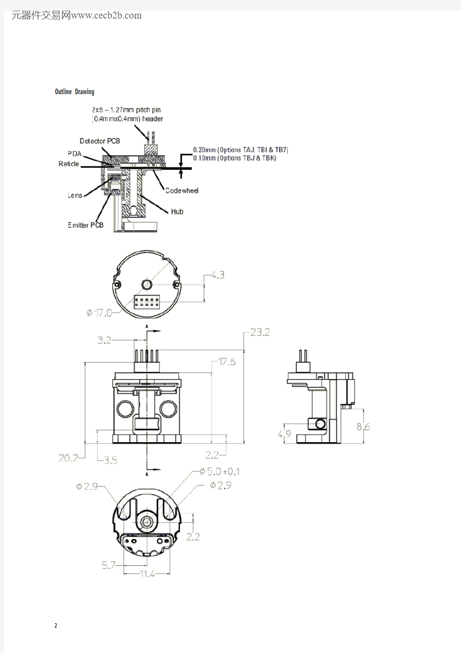
Outline Drawing
Output Waveforms
Theory of Operation
The AEDA-3200 translates rotary motion of a shaft into a three channel digital output. The AEDA-3200 series has five key parts: a single light emitting diode (LED) light source, a photodetector IC with a set of uniquely config-ured photodiodes, an interpolator IC, a line driver IC and a pair of lenses.
This light is used to produce internal signals A and A -, and B and B -
.
As part of the “push-pull” detector system, these signals are fed through comparators and line driver that are part of the signal processing circuitry to produce the final outputs for channels A.
The AEDA-3200 is available for cycles per revolution (CPR) of 2500 to 7500. This translates to a maximum resolution of 30000 counts after quadrature decode (4X).
Definitions Count (N): N refers to the cycles per revolution (CPR) of the encoder output. One Cycle (C): 360 electrical degrees (°e).
One Shaft Rotation: 360 mechanical degrees, N cycles (rotary motion only).
Phase (φ): The number of electrical degrees between the center of the high state on the channel A and the center of the high state of channel B. This value is nominally 90°e.Pulse Width (P): The number of the electrical degrees that an output is a high-level during one cycle, nominally 180°e or 1/2 a cycle.
Pulse Width Error (?P): The deviation in electrical degrees of the pulse width from its ideal value of 180°e.
Index Pulse Width (Po): The number of electrical degrees that an index is high during one full shaft rotation. This value
is nominally 90°e or 1/4 cycle.
State Width (S): The number of the electrical degrees be-tween a transition in the output of the channel B. There are 4 states per cycle, each nominally 90°e.State Width Error (?S): The deviation in electrical degrees of each state width from its ideal value of 90°e.Direction of Motor Rotation
When the codewheel rotates in a clockwise direction, channel A will lead channel B (Figure 1 illustrates the defi-nition of clockwise direction of codewheel rotation). When the codewheel rotates in a counter-clockwise direction,
channel B will lead channel A.Figure 1. Viewed from the PCB encoder end.
Recommended Operating Conditions
Parameter Symbol Min. Typical Max. Units Notes Temperature T A -40 25 125 °C
Supply Voltage V CC 4.5 5.0 5.5 Volts Ripple <100 mVp-p Frequency f 125 750 kHz f = RPM x CPR
60
Absolute Maximum Ratings Storage Temperature
-40°C to 125°C Operating Temperature
-40°C to 125°C Supply Voltage 4.5 V to 5.5 V Output Voltage -0.5 V to V cc Output Current per Channel 20 mA Frequency
750 kHz
Maximum Frequency and RPM
CPR Maximum Frequency (kHz) Maximum RPM 22500 750 1 12000 5000 750 9000 6000 750 7500 7200 750 6250 7500
750
6000
Note:
1. Maximum frequency will be lower due to limitation in maximum RPM.
2. Maximum mechanical limit is 12000 RPM, operating limit is dependent on the maximum operating frequency.
Electrical Characteristics
Electrical characteristics over recommended operating conditions. Typical values at 2 o C. Parameter Symbol Min. Typical Max. Units
55 80 mA Supply Current I
CC
2.5
3.4 V High level Output Voltage V
OH
Low level Output Voltage V
0.3 0.5 V
OL
Encoding Characteristics
Encoding characteristics over recommended operating conditions. Typical values at 2 o C. Parameter Symbol Typical Max. Units
Pulse Width Error ?P 5 85 °e
State Width Error ?S 5 60 °e
Phase Error ?φ 1 40 °e
Mechanical Characteristics
(Refer to page 2 for details.)
Parameter Dimension/Details Tolerance Units Standard Shaft Diameters 2 mm diameter maximum * -.002/-.007 (-.0001/-.0003) mm (in) Mounting Screw Size: M2.5 x 0.45 mm
(Recommended Length 6 mm)
* Note:
1. Using a step shaft, maximum shaft diameter is 4 mm.
HEDS-89 0 Mechanical Alignment Tool.
Pin Assignments
Pin Signal Description Pin 1 A+ Digital Output Pin 2 A- Digital Output Pin 3 Gnd Ground Pin Pin 4 Gnd Ground Pin Pin 5 B+ Digital Output Pin 6 B- Digital Output Pin 7 Vcc Input Voltage Pin 8 Vcc Input Voltage Pin 9 I+ Digital Output Pin 10
I-
Digital Output
Notes:
1. Both Pin 7 and Pin 8 must be connected to Vcc.
2. Either Pin 3 or Pin 4 must be connected to Gnd.
Mating Connector
AEDA-3200 requires a 5 x 2 (1.27 mm x 1.27 mm) female IDC Connector. An example of the suggested mating connectors is Samtec (https://www.wendangku.net/doc/f417004446.html,) part number: FFSD-05-D-x-01-N. The cable used is 0.635 mm pitch flat ribbon cable.
Electrical Interface
Avago recommends National Semiconductor DS26C32AM Quad Differential Line Receiver or compatible as line receiv-
er. Unused pin should be grounded for noise reduction.
Alignment Considerations
The mechanical alignment tool is intended to absorb normal installation misalignment and runouts. To achieve the opti-mum performance, user should minimize misalignment. Complete instructions for AEDA-3200 installation can be found in Application Note 5080, Avago AEDA-3200-T Mechanical Mounting and Installation Consideration. AEDA-3200 Mechanical Alignment tool part number is HEDS-8940.
Ordering Information
Alignment Tool Remark
HEDS-8940
Mechanical Alignment Tool
For product information and a complete list of distributors, please go to our web site: https://www.wendangku.net/doc/f417004446.html, Avago, Avago Technologies, and the A logo are trademarks of Avago Technologies, Limited in the United States and other countries.Data subject to change. Copyright ? 2006 Avago Technologies, Limited. All rights reserved. Obsoletes AV01-0175EN AV01-0619EN - November 1, 2006
A E D A - 3 2 0 0 - T
Resolution Options (CPR)Counts After 4x Decoding
A J
B 1B 7B J B K 2,5005,0006,0007,2007,500
10,00020,00024,00028,80030,000