2009_OC_Configurable three-dimensional optical

Con?gurable three-dimensional optical cage generated from cylindrical vector beams
Xi-Lin Wang,Jianping Ding,Jian-Qi Qin,Jing Chen,Ya-Xian Fan,Hui-Tian Wang *
Nanjing National Laboratory of Microstructures and Department of Physics,Nanjing University,Nanjing 210093,China
a r t i c l e i n f o Article history:
Received 22December 2008
Received in revised form 6May 2009Accepted 21May 2009
PACS:42.25.Ja 42.40.Jv 42.60.Jf 42.50.Wk
Keywords:Polarization Vector ?eld
Computer-generated holograms Optical cage
Optical tweezers
a b s t r a c t
We propose a new approach to generate a controllable three-dimensional (3D)optical cage by double-mode cylindrical vector beam in the vicinity of focus,by controlling the polarization state of beam.The simulation results show that the 3D optical cage of spheroid surface shape with a sharp dark region surrounded by a uniform optical barrier with a maximum deviation of 2%is achieved.The ?nite-differ-ence time-domain calculation of optical force validates that such a kind of 3D optical cage has the trap-ping capability of the low-refractive-index particles with the size being much smaller than the light wavelength.
ó2009Elsevier B.V.All rights reserved.
1.Introduction
In various optical equipments,instruments,and devices,differ-ent purposes require that the focused light beam should have dif-ferent shapes near the focal plane.The shape of optical focus is thereby desired to be controllable.It is well known that the shape
can be modi?ed by the design of phase distribution.Introducing the dimension of polarization is paramount because the control in the shape of optical focus becomes more ?exible.Naturally,the vector beams with the controllability of polarization provoke extensive interest [1–10].The vector beams could also generate the three-dimensional (3D)central hollow focus,besides the sha-per focus.The 3D hollow focus surrounded by regions of higher intensity has been attractive due to its peculiar property as an opti-cal cage,which can provide a dark optical trap for capturing parti-cles [4–8]or an erase beam for realizing superresolution ?uorescence microscopy [9,10].Kozawa and Sato generated an optical cage from a double-ring-shaped radially polarized beam [4].Arlt and Padgett produced a dark spot by superposing two La-
guerre–Gaussian modes with different Gouy phases [11].The above two techniques can produce only a nonuniform optical cage,in which the optical barrier along the beam axis is higher than that along the radial direction.Bokor and Davidson chose two counter-propagating radially polarized Laguerre–Gaussian beams to realize a hollow dark spherical spot enclosed by relatively uniform optical barrier [12].However their methods require a sophisticated focus-ing system and elaborate optical alignment.Radially polarized beams with a circular p phase plate [13]have also been used to produce a 3D optical cage [14],wherein the barrier of cages achieved a uniformity of about 85%.In this Letter we present a new method to produce a controllable 3D optical cage by tightly focusing a double-mode cylindrical vector beam.The double-mode vector beam consists of two polarization states in the transverse section.Such a vector beam could be easily generated by the inter-ferometric method,as described in our previous work [15].The barrier of the optical cage proposed here can be adjusted so that a uniformity of about 98%is obtained.
2.3D optical cage with an almost-uniform optical barrier
It is well known that tightly focusing a radially polarized beam can produce a strong electric ?led along the beam axis near the
0030-4018/$-see front matter ó2009Elsevier B.V.All rights reserved.doi:10.1016/j.optcom.2009.05.045
*Corresponding author.Tel.:+862583594662;fax:+862583595535.
E-mail addresses:jpding@https://www.wendangku.net/doc/fb17807445.html, (J.Ding),htwang@https://www.wendangku.net/doc/fb17807445.html, (H.-T.Wang).Optics Communications 282(2009)3421–3425
Contents lists available at ScienceDirect
Optics Communications
journal homepage:www.else v i e r.c o m /l o ca t e /o p t c o m
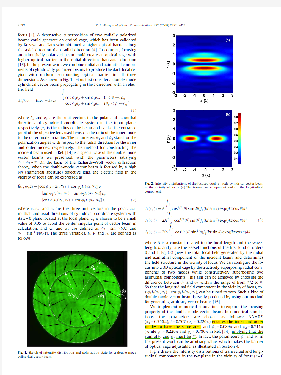
focus[1].A destructive superposition of two radially polarized beams could generate an optical cage,which has been validated by Kozawa and Sato who obtained a higher optical barrier along the axial direction than radial direction[4].In contrast,focusing an azimuthally polarized beam could create an optical cage with higher optical barrier in the radial direction than axial direction [16].In the present work we combine radial and azimuthal compo-nents of cylindrically polarized beams to produce the dark focal re-gion with uniform surrounding optical barrier in all three dimensions.As shown in Fig.1,let us?rst consider a double-mode cylindrical vector beam propagating in the z direction with an elec-tric?eld
Eeq;/T?E q^e qtE/^e/?
cos/1^e qtsin/1^e/;0 cos/2^e qtsin/2^e/;t q0 ( ; e1T where^e q and^e/are the unit vectors in the polar and azimuthal directions of cylindrical coordinate system in the input plane, respectively.q0is the radius of the beam and is also the entrance pupil of the objective lens used here.t is the ratio of the inner mode to the outer mode in radius.The parameters/1and/2stand for the polarization angles with respect to the radial direction for the inner and outer modes,respectively.The method for constructing the incident beam used in Ref.[14]is a special case of the double mode vector beams we presented,with the parameters satisfying /1+/2=p.On the basis of the Richards–Wolf vector diffraction theory,when the double-mode vector beam is focused by a high NA(numerical aperture)objective lens,the electric?eld in the vicinity of focus can be expressed as ~Eer;u;zT??cos/ 1 I1ea1;a2Ttcos/2I1ea2;a3T ^e r t?sin/1I2ea1;a2Ttsin/2I2ea2;a3T ^e u t?cos/1I3ea1;a2Ttcos/2I3ea2;a3T ^e ze2T where^e r;^e u,and^e z are the three unit vectors in the polar,azi-muthal,and axial directions of cylindrical coordinate system with its z=0plane located at the focal plane.a1is chosen to be a small value of0.05to avoid the center singular point of vector beam in calculation,and a3and a2are de?ned as a3?sinà1eNATand a2?sinà1eNAátT.The three variables,I1,I2and I3,are de?ned as follows I1en;fT?A Z f n cos1=2ehTsine2hTJ1ekr sin hTexpejkz cos hTd h I2en;fT?2A Z f n cos1=2ehTsinehTJ1ekr sin hTexpejkz cos hTd h I3en;fT?2iA Z f n cos1=2ehTsin2ehTJ0ekr sin hTexpejkz cos hTd h e3T where A is a constant related to the focal length and the wave-length,J0and J1are the Bessel functions of the?rst kind of orders 0and1.Eq.(2)gives the total focal?eld generated by the radial and azimuthal component of the incident beam,and determines the?eld structure in the vicinity of focus.We can con?gure the fo-cus into a3D optical cage by destructively superposing radial com-ponents of two modes while constructively superposing two azimuthal components.This aim can be achieved by choosing the difference between/1and/2within the range of from p/2to p. So that the longitudinal?eld component in the vicinity of focus,co-s/1I3(a1,a2)+cos/2I3(a2,a3),can be tuned to zero.Such a kind of double-mode vector beam is easily produced by using our method for generating arbitrary vector beams[15]. We implement numerical simulations to explore the focusing property of the double-mode vector beam.In numerical simula-tions,the parameters are chosen as follows:NA=0.9 (a 3 =0.356p),t=0.707(a2=0.220p)ensures the inner and outer modes to have the same area,and/1=0.089p and/2=0.711p (while/1=0.220p and/2=0.780p in Ref.[14],implying that the sum of/1and/2must be p).In fact,the parameters/1and/2in the present work can be arbitrary value,which makes the barrier of optical cage adjustable,as illustrated in Section4. Fig.2draws the intensity distributions of transversal and longi-tudinal components in the r–z plane in the vicinity of focus(r=0 Sketch of intensity distribution and polarization state for a double-mode cylindrical vector beam.Fig.2.Intensity distributions of the focused double-mode cylindrical vector beam in the vicinity of focus.(a)The transversal component and(b)the longitudinal component. 3422X.-L.Wang et al./Optics Communications282(2009)3421–3425 and z =0).One can see that the transversal ?eld provides a high optical barrier in the radial direction,while the longitudinal ?eld offers a high optical barrier,and both optical barriers have the rota-tional symmetry about the axial direction and the mirror symme-try with the focal plane.Consequently,a 3D central hollow dark optical cage can be generated from the total ?eld in the vicinity of the focus,as shown by the contour ?gure in Fig.3a.To clearly show the optical barrier surrounding the optical cage,Fig.3b plots the intensity pro?le by the 3D surface ?gure in the r –z plane near the focus.The optical cage is surrounded by a near uniform,which exhibits a spheroid surface shape with an ellipticity of 3.13and has a size of 1.36k in the longitudinal direction and of 0.43k in trans-verse direction.To further con?rm the uniformity of optical barrier, we plot the intensity distributions in three typical directions,A ,B and C as shown in Fig.3a,in which A and C are along the radial and axial directions while B is the direction with an angle of 0.146p with respect to the axial direction (in this direction there has the lowest optical barrier).Fig.3c plots the intensity distributions,I A ,I B and I C ,in the three directions,A ,B and C .It can be seen that the optical barriers are the same in the A and C directions while the optical barrier in the B direction is 98%of that in the A and C directions (with a maximum deviation of 2%).3.Trapping of particles with low refraction index The optical tweezers based on focused beam has proven to be a very useful tool for the manipulation of microscopic particles [5].It is known that a bright focus cannot trap particles with refraction index lower than that of the surrounding medium,because the low-refractive-index particles will be repelled from the highest intensity.In general,a focus with lower intensity in center is needed for trapping the low-refractive-index particles.The optical cage proposed in this paper provides a promising technique for trapping the low-refractive-index particles.To con?rm the optical trapping property of the optical cage,we have implemented the improved ?eld ?nite-difference time-domain (FDTD)method to evaluate the optical force acting on the low-refractive-index parti-cle.The details of the FDTD could be found in our newly published paper .The low-refractive-index particle used for simulation is the droplets diffused in the acetophenone solution,which X.-L.Wang et al./Optics Communications 282(2009)3421–34253423 resembles an arrangement made by Mohanty et al.in their exper-iment[18].The specimen solution is con?ned between glass cover-slip and slide.The incident light beam used has a wavelength of 532nm and a power of1W,and the radius of droplet is60nm. The refractive indices of the water and the acetophenone are 1.33and1.53at532nm,respectively.Despite that the rigorous theoretical treatment should take into account the in?uence of the interface effect on the focal intensity distribution[19],we do not carefully consider the situation when the refractive index mis-matches.The in?uence of interface of sample cell on focusing can be neglected due to the following two facts:(i)an oil-immersion objective is generally used for tight focusing,and consequently, the refractive indices of oil and coverslip are matched and(ii)the refractive index of coverslip is nearly close to that of acetophenone. We calculate the optically induced forces in three directions A, B and C(as shown in Fig.3),respectively.Fig.4a furnishes the cal-culated results,the components of forces on the droplet in the three directions,F A,F B and F C,as functions of position.It can be found that in the curve F A,the balance position is always at the beam axis(r=0),that is to say,the droplet will be pulled back to the axis because the droplet always receives a restoring force pointing toward the axis once the droplet moves away from the axis along the radial direction.In contrast,we can see from the curve F C that the balance position is not exactly the focal plane (z=0)while is located behind the focal plane,since the scattering force always points toward the propagation direction of light beam between two kinds of optical forces(gradient and scattering forces).Of course,we can easily understand that in the B direction, the balance position has a smaller deviation from the focus,be-cause the scattering force has a fraction of contribution in the B direction.In addition,the water droplet inside the acetophenone must undergoes a?otage toward up,which can be in part counter-acted by the scattering force toward down when the beam propa-gates toward down,and thus the balance position should be more close to the focal plane.The optical cage we designed could trap the low-refractive-index particles in three dimensions,because Mohanty et al.have validated that the hollow focusing?eld could trap the low-refractive-index particles in theory and experiment [18]. Since the azimuthally polarized beam can also be focused into a hollow focus,it is interested to explore the trapping property of the optical cage formed by the azimuthally polarized beam.We calcu-late the optical force offered by the azimuthally polarized beam under the same conditions(including incident power,particle and focusing parameters).The results plotted in Fig.4b indicate that the trapping of the low-refractive-index particle is possible in the transversal dimension(A direction)while impossible in the axial direction(C direction),that is to say,the particle can be trapped in two dimensions only while cannot be trapped in three dimensions simultaneously,when the azimuthally polarized light is used to construct the optical cage. 4.Controllability of optical cage We now explore the controllability of optical cage generated by the double-mode vector beam.In fact,the intensity distribution of the optical cage barrier can be accurately controlled by changing the polarization angle/1and/or/2.As an example,/1is?xed at /1=0.089p,the calculated result in Fig.5shows that the peak intensity ratio of the axial direction to the radial one increases Intensity distribution of the generated optical cage when/1=0.089 p.(a)In contour?gure,(b)surface?gure,and(c)intensity pro?le of A and C. 3424X.-L.Wang et al./Optics Communications282(2009)3421–3425 monotonously with the augment of/2.When/2is0.711p,the ax-ial direction is the same as the radial direction in peak intensity and then a uniform3D optical cage can be generated in the focal region.The intensity distribution of the optical cage for /2=0.791p is shown by the contour?gure in Fig.6a and by the 3D surface?gure in Fig.6b,respectively,in which the optical bar-rier in the radial direction is a half of that in the axial direction.To clearly depict the intensity distributions of the optical cage,Fig.6c plots the intensity as a function of position in the A and C direc-tions.In contrast,when/2=0.632p,the optical barrier in the axial direction is a half of that in the radial direction(as shown in Fig.7). Consequently,the shape of the optical cage can be?exibly con?g-ured,i.e.,its trapping property is controllable,by modifying the polarization state of the double-mode vector beam.It should be pointed out that the A and C directions in Figs.6and7are the same as that in Fig.3. 5.Conclusions In summary,we have proposed a novel way to generate the3D optical cage from double-mode cylindrical vector beam.The shape of the optical cage can be easily controlled by adjusting the polar-ization state of the incident beam.Such a kind of optical cage can be applied to optical trapping of the low-refractive-index particle. It can also be anticipated that such optical cage may?nd applica-tion for the trapping of cold atoms[7,8].Our FDTD simulations have validated the signi?cance of polarization modulation in improving the property of optical cage.We conclude that the opti-cal cage can be more elaborately tailored if more polarization modes are incorporated into focus design. Acknowledgements This work is supported in part by the NSFC under Grant Nos. 10874078and60608006,the Natural Science Foundation of Jiang-su Province under Grant No.BK2007126,and the State Key Pro-gram for Basic Research of China under Grant No.2006CB921805. References [1]K.S.Youngworth,T.G.Brown,Opt.Express7(2000)77. [2]R.Dorn,S.Quabis,G.Leuchs,Phys.Rev.Lett.91(2003)233901. [3]K.G.Lee,H.W.Kihm,J.E.Kihm,W.J.Choi,H.Kim,C.Ropers,D.J.Park,Y.C.Yoon, S.B.Choi,D.H.Woo,J.Kim,B.Lee,Q.H.Park,C.Lienau,D.S.Kim,Nat.Photon.1 (2007)53. [4]Y.Kozawa,S.Sato,Opt.Lett.31(2006)820. [5]A.Ashkin,J.M.Dziedzic,J.E.Bjorkholm,S.Chu,Opt.Lett.11(1986)288. [6]K.T.Gahagan,G.A.Swartzlander,Opt.Lett.21(1996)827. [7]T.Kuga,Y.Torii,N.Shiokawa,T.Hirano,Y.Shimizu,H.Sasada,Phys.Rev.Lett. 78(1997)4713. [8]R.Ozeri,L.Khaykovich,N.Friedman,N.Davidson,J.Opt.Soc.A B17(2000) 1113. [9]S.W.Hell,J.Wichmann,Opt.Lett.19(1994)780. [10]P.T?r?k,P.R.T.Munro,Opt.Express12(2004)3605. [11]J.Arlt,M.J.Padgett,Opt.Lett.25(2000)191. [12]N.Bokor,N.Davidson,Opt.Lett.31(2006)149. [13]W.Chen,Q.Zhan,https://www.wendangku.net/doc/fb17807445.html,mun.265(2006)411. [14]N.Bokor,N.Davidson,https://www.wendangku.net/doc/fb17807445.html,mun.279(2007)229. [15]X.L.Wang,J.P.Ding,W.J.Ni,C.S.Guo,H.T.Wang,Opt.Lett.32(2007)3549. [16]Q.Zhan,J.Leger,Opt.Express10(2002)324. [17]J.Q.Qin,X.L.Wang,D.Jia,J.Chen,Y.X.Fan,J.P.Ding,H.T.Wang,Opt.Express17 (2009)8407. [18]S.K.Mohanty,R.S.Verma,P.K.Gupta,Appl.Phys.B87(2007)211. [19]Y.Zhao,https://www.wendangku.net/doc/fb17807445.html,ne,J.S.Edgar,G.D.M.Jeffries,D.McGloin,D.T.Chiu,Appl.Phys. Lett.92(2008)161111. Intensity distribution of the generated optical cage when/1=0.089 0.632p.(a)In contour?gure,(b)surface?gure,and(c)intensity pro?le directions. X.-L.Wang et al./Optics Communications282(2009)3421–34253425