cgy 59w中文资料
GaAs MMIC
CGY 59W
Data Sheet
?
Low noise preamplifier for mobile communication (PCN, DECT, GSM) in 2.7 V to 6 V systems ?Biased monolithic microwave IC (MMIC)?Easily matchable to 50 W ?No bias coil needed
?Single positive supply voltage ?Low noise figure and high gain
NF = 1.3 dB, G = 16.5 dB @ 3 V, 950 MHz (typ.)NF = 1.7 dB, G = 12 dB @ 3 V, 1.85 GHz (typ.)?Low power consumption
?Frequency range 200 MHz … 2.5 GHz ?Miniature package P-SOT363-6-1
ESD: E lectro s tatic d ischarge sensitive device, observe handling precautions!Type Marking Ordering Code (taped)Package CGY 59W
Y5s
Q62702 - G69
P-SOT363-6-1
Maximum Ratings Symbol Value Unit Drain voltage V D 8V Channel temperature T Ch 150
°C Storage temperature range
T stg – 55 … + 150°C Total power dissipation (T S ≤ t.b.d. °C)1)
1)
Please care for sufficient heat dissipation on the pcb!
P tot
80
mW
Thermal Resistance
Symbol Value Unit Channel-soldering point (GND)R thChS ≤ t.b.d.K/W Junction-ambient 1)
1)
Package mounted on alumina 15 mm × 16.7 mm × 0.7 mm.
R thJA
< t.b.d.
K/W
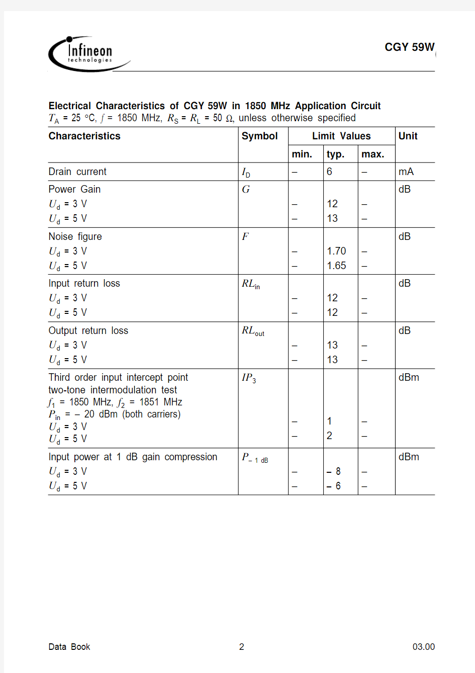
Electrical Characteristics of CGY 59W in 1850 MHz Application Circuit T A = 25 °C, f = 1850 MHz, R S = R L = 50 ?, unless otherwise specified Characteristics Symbol
Limit Values Unit
min.
typ.max.Drain current I D –
6–mA Power Gain U d = 3 V U d = 5 V G
––1213––
dB
Noise figure U d = 3 V U d = 5 V F
––
1.701.65––
dB
Input return loss U d = 3 V U d = 5 V
RL in
––
1212––
dB
Output return loss U d = 3 V U d = 5 V
RL out
––
1313
––
dB
Third order input intercept point two-tone intermodulation test f 1 = 1850 MHz, f 2 = 1851 MHz P in = – 20 dBm (both carriers)U d = 3 V U d = 5 V
IP 3
––12––
dBm Input power at 1 dB gain compression U d = 3 V U d = 5 V
P – 1 dB
––
– 8– 6
––
dBm
Figure1
Figure21850 MHz Application (PCN, DECT)
Figure3PCB - Layouts for Application Circuits
1850 MHz PCN -, DECT - application board
PCB - data: Glass fiber teflon board (double sided) TACONIC TLX-9-0150-CH/CH,εr = 2.45, thickness = 0.4 mm
Typical S- and Noise-Parameters
V
= 3 V, Z o = 50 ?
D
f S11S21S12S22 GHZ MAG ANG MAG ANG MAG ANG MAG ANG 0.10.999– 4 4.30– 1770.006– 750.261– 17 0.20.998– 6.6 4.32– 1730.01197.60.251– 10 0.30.997– 10 4.30– 1670.010940.247– 11 0.40.982– 14 4.261610.016760.238– 12 0.50.970– 18 4.241560.019780.232– 13 0.60.958– 21 4.161510.020780.226– 15 0.70.940– 24 4.131460.023730.221– 16 0.80.918– 27 4.021410.026790.218– 18
0.90.889– 32 3.911360.031790.209– 22
1.00.870– 34 3.821320.033760.195– 21 1.10.845– 37 3.761280.036750.189– 23 1.20.829– 39 3.631230.039730.186– 24 1.30.806– 42 3.581190.041720.177– 24 1.40.789– 45 3.471150.043710.173– 24 1.50.765– 47 3.391110.046710.166– 24 1.60.748– 50 3.291070.046720.159– 24 1.70.725– 52 3.211040.051710.154– 22 1.80.703– 54 3.141000.051710.147– 21
1.90.695– 56 3.08970.055690.140– 18
2.00.664– 58 2.98930.056710.135– 15 2.10.644– 59 2.86900.059700.129– 13 2.20.631– 61 2.83860.062690.123– 9.6 2.30.605– 63 2.79830.063690.114–
3.4 2.40.590– 65 2.70800.064690.109 2.7 2.50.570– 67 2.65760.065700.1069.2
S- and noise-parameters are also available on CD-ROM.f
F min
G opt
R N
MAG
ANG GHz dB –deg ?0.8 1.150.771959.71.0 1.190.742256.41.2 1.240.722754.01.4 1.310.713251.81.6 1.390.703649.61.8 1.490.683947.32.0
1.62
0.66
43
43.9
Typical S- and Noise-Parameters V D = 5 V, Z o = 50 ?f S11
S21S12
S22GHZ MAG ANG MAG ANG MAG ANG MAG ANG 0.10.998– 3.4 4.99– 1770.007– 730.366– 150.20.997– 6.8 4.97– 1730.008300.331– 8.80.30.995– 10 4.99– 1670.012960.328– 9.20.40.976– 14 4.981610.012820.316– 110.50.963– 17 4.911560.014890.318– 120.60.957– 21 4.811510.020770.306– 140.70.942– 24 4.761460.022830.302– 160.80.920– 27 4.631410.027790.297– 170.90.887– 31 4.501360.031790.289– 211.00.871– 33 4.401320.033750.276– 211.10.846– 36 4.311280.035750.269– 221.20.826– 39 4.161230.037750.263– 221.30.807– 41 4.121190.039700.256– 241.4
0.788
– 44
4.01
116
0.042
73
0.246
– 24
S- and noise-parameters are also available on CD-ROM.
1.50.762– 46 3.911120.043720.240– 241.60.744– 49 3.771080.047710.234– 251.70.723– 51 3.691050.048710.229– 241.80.703– 53 3.601010.051700.221– 231.90.687– 55 3.50980.052710.215– 22
2.00.665– 57
3.42940.054720.208– 212.10.647– 58 3.28910.057720.203– 202.20.636– 60 3.25880.058700.193– 592.30.611– 62 3.20840.060690.184– 172.40.595– 63 3.14820.062700.176– 142.5
0.573
– 66
3.06
78
0.063
71
0.172
– 11
f
F min
G opt
R N
MAG
ANG GHz dB –deg ?0.8 1.130.761858.51.0 1.160.742156.31.2 1.210.732752.71.4 1.260.723049.11.6 1.330.703448.51.8 1.420.683845.22.0
1.55
0.66
42
43.4
Typical S- and Noise-Parameters (cont’d)V D = 5 V, Z o = 50 ?f S11S21S12S22GHZ MAG ANG MAG ANG MAG ANG MAG ANG
Figure4Application Circuit for Measuring S-Parameters
f = 200 MHz to 2.5 GHz
1) Caution! DC - decoupling capacitors are not integrated in device
Package Outlines
Sorts of Packing
Package outlines for tubes, trays etc. are contained in
our Data Book “Package Information”.
Dimensions in mm SMD = Surface Mounted Device