How to do MTBF 如何计算MTBF

MTBF Failure Rate Calculations
FAILURE RATES
Almost all components on a card exhibit the famous bathtub curve when plotting failure rate against time.
The effects of the infant mortality period can be dramatically reduced by burn-in, on the component level or on the product level or a combination of the two. The failure rate during the useful life of the component is nearly constant. It is often expressed as % failure/1000 hours or as a number of
failures/109o D hours (FIT). Pro-Logs standard failure rate is the expected failure rate during the useful period for products designed and manufactured by Pro-Log.
After the useful period, which is longer than 10 years for most semiconductors, the failure rate starts to increase. Wear-out failures characterize this period. Pro-Log started calculating MTBF over ten years ago with the standard failure rates for each component type used (see table). These failure rates were based on data from MIL-HDBK-217C and established failure rates from large well-known computer companies. Pro-Log standard failure rates will be periodically adjusted based on five years of warranty repair data.
A component has many failure modes, i.e., some of the failure modes most commonly found in an IC are bad lead bonding, bad die-attach, surface contamination of the chip, defects anywhere in one or more of the 10 (or more) masks (working plates), defects in the monocrystaline structure, out of spec diffusion, implantation or deposition processes and many more. Each of these failure modes has a different activation energy, i.e., they will exhibit and individual temperature dependency. In addition, each individual component on a PW
B is exposed to a different stress level. The task of calculating the contribution of each failure mode for every component is far beyond what can be economically justified. experience has shown that using a standard failure rate for each component yields a failure rate for the system that is within tolerable margins.
CALCULATION OF MTBF
The failure rate for a card (or system) is calculated by using the standard failure rate for each component type times the number of components of that type and adding that product for all component types on the card. The MTBF is the inverse of the failure rate.
The average environment for a card is assumed to be approximately 55 i.e., T average =
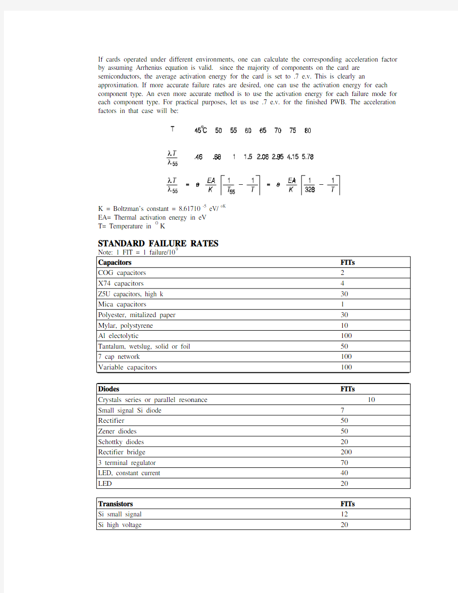
If cards operated under different environments, one can calculate the corresponding acceleration factor by assuming Arrhenius equation is valid. since the majority of components on the card are semiconductors, the average activation energy for the card is set to .7 e.v. This is clearly an approximation. If more accurate failure rates are desired, one can use the activation energy for each component type. An even more accurate method is to use the activation energy for each failure mode for each component type. For practical purposes, let us use .7 e.v. for the finished PWB. The acceleration factors in that case will be:
K = Boltzman’s constant = 8.61710-5 eV/ oK
EA= Thermal activation energy in eV
T= Temperature in O K
STANDARD FAILURE RATES
Note: 1 FIT = 1 failure/109
Capacitors FITs
COG capacitors2
X74 capacitors4
Z5U capacitors, high k30
Mica capacitors1
Polyester, mitalized paper30
Mylar, polystyrene10
Al electolytic100
Tantalum, wetslug, solid or foil50
7 cap network100
Variable capacitors100
Diodes FITs
Crystals series or parallel resonance10
Small signal Si diode7
Rectifier50
Zener diodes50
Schottky diodes20
Rectifier bridge200
3 terminal regulator70
LED, constant current40
LED20
Transistors FITs
Si small signal12
Si high voltage20
Si high power50 Si Darlington70
Resistors FITs Metal film, 1% IT, 3% EOL7 Carbon film, 3% IT, 8% EOL10 Carbon film, 5% IT, 10% EOL10 Resistor network SIP40 Wire wound, low power, 1 watt or less5 Wire wound, high power10 Carbon composition, 5% IT, 20% EOL5 Potential meter200
ICs FITs 74xx & 74LSxx, SSI & MSI30 74xx & 74LSxx, Complex60 74Sxx & 74ASxx, SSI & MSI70 74ALSxx, SSI & MSI50 74Cxx, 74HCxx, 74HCTxx, SSI & MSI50 Controllers, Timers100
One shots:FITs 74LS221, 7412350 74HC22170 74ACT37370 Optical Isolators50 VLSIs, CPUs170 Line Drivers & Receivers:
74LS240, 74S244, 74LS245100 74ALS240, 74ALS244, 74ALS245130 1488, 1489, 75175, 75174
74HC240, 74HC244, 74HC245100 74HCT240, 74HCT244, 74HCT245100 74ACT240, 74ACT244, 74ACT245150 Linear Devices:
Complex, Instrumentation Amp200 Op Amps, Comparators130 Programmable Devices, bipolar120 Programmable Devices, MOS, CMOS120 Memories:
Old static RAMs, <<64K150 SRAMS, 64K120 SRAMS, 128K150 SRAMS, 256K170 DRAMS, 64K150 DRAMS, 256K180
DRAMS, 512K200
Switches FITs
Toggle, Slide300
Rotary, BCD800
Relays FITs
Reed400
Solid State150
Miscellaneous
Transformers, inductors10 FITs Throughhole Solder joints.2 FITs/solder joint Surface-mount solder joint 2 FITs/solder joint PWB connector 3 FITs/contact PWB opens and shorts100 FITs
IC sockets, gastight seal.5 FITs/contact Hybrid oscillator150 FITs
I/O connectors 1 FIT/contact
IC socket, machined pin 1 FIT/contact
*Switching power supply,TA=40o
*Brushless fan, TA=40o
*Floppy disk40,000 POH
*Suggested failure rates.
Check with vendors for their specific data.
The MTBF for a card (or a system) is found by adding the failure rates for each component type and taking the inverse. Failure rate for each component type is the product of the number of components of that type and the failure rate for the component.