MEK350-02DA中文资料

Features
q International standard package with DCB ceramic base plate q Planar passivated chips q Short recovery time q Low switching losses q Soft recovery behaviour q Isolation voltage 3600 V~q
UL registered E 72873
Applications
q Antiparallel diode for high frequency switching devices
q Free wheeling diode in converters and motor control circuits q Inductive heating and melting
q Uninterruptible power supplies (UPS)q
Ultrasonic cleaners and welders
Advantages
q High reliability circuit operation q Low voltage peaks for reduced protection circuits q Low noise switching q
Low losses
Dimensions in mm (1 mm = 0.0394")
0.531.297550375356180030003600
-40...+150-40...+125
110
288002930023300238002400264021602380150
12.79.6502.25-2.75/20-254.50-5.50/40-481500.800.98260
0.921.070.2280.143
3
280x I FAVM rating includes reverse blocking losses at T VJM , V R = 0.6 V RRM , duty cycle d = 0.5Data according to IEC 60747
IXYS reserves the right to change limits, test conditions and dimensions
300150
200100920015
911
875123
V RSM V RRM
Type
V V 200
200
MEK 350-02DA
Symbol Test Conditions
Maximum Ratings
I FRMS
T C =°C
A I FAVM ??x T C =°C; rectangular, d = 0.5
A I FRM t P < 10 m s; rep. rating, pulse width limited by T VJM A I FSM
T VJ = 45°C;
t = 10 ms (50 Hz), sine A t = 8.3 ms (60 Hz), sine
A T VJ = 150°C;t = 10 ms (50 Hz), sine
A t = 8.3 ms (60 Hz), sine
A I 2t
T VJ = 45°C;
t = 10 ms (50 Hz), sine A 2s t = 8.3 ms (60 Hz), sine
A 2s T VJ = 150°C;t = 10 ms (50 Hz), sine
A 2s t = 8.3 ms (60 Hz), sine
A 2s T VJ °C T stg °C T Smax °C P tot T C = 25°C
W V ISOL 50/60 Hz, RMS t = 1 min V~I ISOL £ 1 mA t = 1 s V~
M d Mounting torque (M6)
Nm/lb.in.Terminal connection torque (M6)Nm/lb.in.
d S Creeping distanc
e on surface mm d A Strike distance through air
mm a Maximum allowable acceleration
m/s 2Weight g
Symbol Test Conditions Characteristic Values (per diode)
typ.max.
I R
T VJ = 25°C V R = V RRM
mA T VJ = 25°C V R = 0.8 ? V RRM mA T VJ = 125°C V R = 0.8 ? V RRM mA V F
I F = A;T VJ =125°C V T VJ =25°C V I F = A;T VJ =125°C V T VJ
=25°C
V V T0
For power-loss calculations only V r T m W R thJH DC current K/W R thJC
DC current
K/W t rr I F = A T VJ = 100°C ns I RM V R = V T VJ = 25°C A -di/dt = A/m s
T VJ = 100°C
A
Fast Recovery Epitaxial Diode (FRED) Module
MEK 350-02 DA
V RRM =200 V I FAVM =356 A t rr =150 ns
1
2
3
0.0
0.4
0.8
050100150200250300350400I F A Constants for Z thJS calculation:i R thi (K/W)t i (s)1 0.0020.082 0.0080.0243 0.0540.1124
0.164
0.464
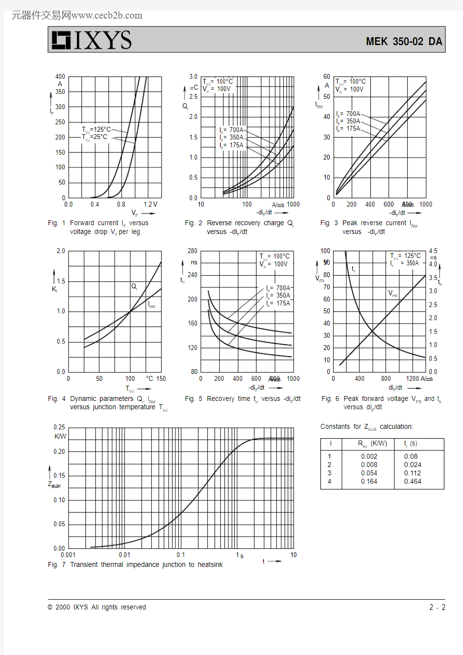
Fig. 3Peak reverse current I RM
versus -di F /dt
Fig. 2Reverse recovery charge Q r
versus -di F /dt
Fig. 1Forward current I F versus
voltage drop V F per leg
Fig. 6Peak forward voltage V FR and t fr
versus di F /dt T VJ =125°C T VJ =25°C