1775230-1中文资料

DESCRIPTION
Tyco Electronics introduces the Ultraminiature Coax Connector and Cable Assembly series products. The UMCC series is an ultra low profile coax interconnect solution that meets the ever growing demand for miniatur-ization in next generation wireless applications. UMCC cable assemblies and connectors are available as dou-ble-ended jumpers and inter-series assemblies, and PCB jack receptacles for board mount applications.
Tyco Electronics specializes in solving tough problems with cable assemblies designed and manufactured to meet the most demanding requirements. Tyco Electronics can engineer custom UMCC solutions to meet special requirements. By making Tyco Electronics your partner in cable assembly design, you reduce risk and gain assurance that you will receive your assembly on time, to specification and within budget.
UMCC – Ultraminiature
Coax Connector &
Cable Assembly Series
RoHS
Ready
APPLICATIONS
?Wireless LAN, Mini PCI
?Mobile Antenna/GPS/Radio Systems
?PDA/ PCS / Cellular Handset
applications
?Wireless Communications systems
(LAN, GSM, PCS, WCDMA, UMTS)
?Remote measuring equipment
KEY FEATURES
?Ultra low profile (2.0mm or 2.5mm
maximum mated height)
?Easy snap on/off mating
?Small footprint on PCB (3mm x 3mm)
?Excellent performance to 6 GHz
?Surface mount and reflow solderable
?360 degree mated rotation
?Available on 0.81mm, 1.13mm, and
1.37mm dia single shield, and
1.32mm dia double shield cable
?Style A receptacles compatible with
Hirose U.FL/U.FL(v) Series
connectors*
?Style B receptacles compatible with
Murata GSC Series connectors
For More Information
Technical Support
I nternet:
https://www.wendangku.net/doc/61905168.html,/products/rfcoax
Email:
https://www.wendangku.net/doc/61905168.html,@https://www.wendangku.net/doc/61905168.html,
US Product Manager Cable Assemblies
— David Stonfer
Phone: 717-986-5950
Email: david.stonfer@https://www.wendangku.net/doc/61905168.html,
US Product Manager Connectors —
Claude de Lorraine
Phone: 717-986-5793
Email: cdelorraine@https://www.wendangku.net/doc/61905168.html,
Europe Product Manager — Rob Smeets
Phone: +31-736246327
Email: r.smeets@https://www.wendangku.net/doc/61905168.html,
USA: 1-800-522-6752
Canada: 1-905-470-4425
Mexico: 01-800-733-8926
C. America: 52-55-1106-0803
South America: 55-112103-6000
Hong Kong: 852-2735-1628
Japan: 81-44-844-8013
UK: +44 (0) 800-267-666
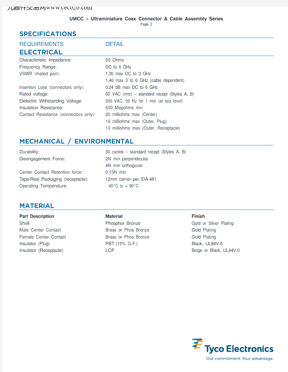
REQUIREMENTS DETAIL
ELECTRICAL
Characteristic Impedance:50 Ohms
Frequency Range:DC to 6 GHz
VSWR (mated pair): 1.30 max DC to 3 GHz
1.40 max 3 to 6 GHz (cable dependent)
Insertion Loss (connectors only):0.24 dB max DC to 6 GHz
Rated voltage:60 VAC (rms) – standard recept (Styles A, B)
Dielectric Withstanding Voltage:200 VAC, 50 Hz for 1 min (at sea level)
Insulation Resistance:500 Megohms min
Contact Resistance (connectors only):20 milliohms max (Center)
10 milliohms max (Outer, Plug)
10 milliohms max (Outer, Receptacle)
MECHANICAL / ENVIRONMENTAL
Durability:30 cycles – standard recept (Styles A, B)
Disengagement Force:2N min perpendicular
4N min orthogonal
Center Contact Retention force:0.15N min
T ape/Reel Packaging (receptacle):12mm carrier per EIA-481
Operating T emperature:- 40°C to + 90°C
MATERIAL
Part Description Material Finish
Shell Phosphor Bronze Gold or Silver Plating Male Center Contact Brass or Phos Bronze Gold Plating
Female Center Contact Brass or Phos Bronze Gold Plating
Insulator (Plug)PBT(15% G.F.)Black, UL94V-0 Insulator (Receptacle)LCP Beige or Black, UL94V-0
CABLE INFORMATION
0.81 mm Diameter
1.13 mm Diameter 1.32mm Diameter 1.37mm Diameter MATERIALS:
Center Conductor
Silver Plated Copper Silver Plated Copper Silver Plated Copper Silver Plated Copper Size Stranded 7/0.05 mm
Stranded 7/0.08 mm
Stranded 7/0.08 mm
Stranded 7/0.10 mm
Dielectric FEP or PFA FEP FEP FEP Size 0.40 mm OD
0.62 mm OD
0.66 mm OD 0.83 mm OD
Shield Silver Plated Copper Braid
Silver Plated Copper Braid
Double SPL Braid
Silver Plated Copper Braid
Coverage > 90%> 90% > 90%> 90%Jacket FEP or PFA FEP > 90%> 90%Size
0.81 mm OD 1.13 mm OD 1.32 mm OD 1.37 mm OD MECHANICAL:
Minimum Bend Radius
5 mm Single Bend 5 mm Single Bend 5 mm Single Bend 5 mm Single Bend 30 mm Continuous Flexing
30 mm Continuous Flexing
30 mm Continuous Flexing
30 mm Continuous Flexing
ELECTRICAL:
Impedance (Ohms)50±250±250±250±2Velocity of Propagation 70%70%70%70%CC Resistance (Ohms/M) 1.4500.7500.5600.354Voltage Rating 60 VAC 60 VAC 60 VAC 60 VAC Attenuation
See Chart
See Chart
See Chart
See Chart
Dimensions are millimeters over inches unless otherwise specified.
-10
-9-8-7-6-5-4-3-2-101 1.52 2.53
3.54
4.55
5.56
Frequency (GHz) 1.37mm OD 1.32mm OD
1.13mm OD 0.81mm OD
UMCC CABLE ATTENUATION
Standard Double Ended Cable Assemblies
Note:Shortest length L is 25mm
Printed Circuit Board
H (MAX)
Receptacle
Part Number Cable Dia Length L UMCC Cable Mates with PCB Mated Height (H)
Connector Type
Receptalce 2015697-30.81mm 50mm I Style B 2.0mm 2015697-10.81mm 100mm I Style B 2.0mm 2015697-20.81mm 200mm I Style B 2.0mm 2015698-40.81mm 50mm II Style A 2.0mm 2015698-20.81mm 100mm II Style A 2.0mm 2015698-30.81mm 200mm II Style A 2.0mm 2015699-30.81mm 50mm III Style A 2.5mm 2015699-10.81mm 100mm III Style A 2.5mm 2015699-20.81mm 200mm III Style A 2.5mm 2015487-6 1.13mm 50mm III Style A 2.5mm 2015487-4 1.13mm 100mm III Style A 2.5mm 2015487-5 1.13mm 200mm III Style A 2.5mm 2015700-3 1.32mm 50mm III Style A 2.5mm 2015700-1 1.32mm 100mm III Style A 2.5mm 2015700-2 1.32mm 200mm III Style A 2.5mm 2015357-3 1.37mm 50mm III Style A 2.5mm 2015357-4 1.37mm 100mm III Style A 2.5mm 2015357-2
1.37mm
200mm
III Style A
2.5mm
4mm REF
L
Total Length (mm)
Standard Tolerance )(mm)
25< L <200+/- 2200< L <700+/- 3700< L <900+/-4900< L
+/-5
Custom cable assembly lengths available.Contact T yco Electronics with specific requirements.
Interseries Cable Assemblies
Part Number Description
Cable Dia Length UMCC Conn
Mated Height
Type (H)2032438-1UMCC Plug to FME Plug 1.37mm 200mm III 2.5mm 2032439-1UMCC Plug to SMA Plug 1.37mm 200mm III 2.5mm 2032440-1UMCC Plug to SMA Blkhd Jack 1.37mm 200mm III 2.5mm 2032441-1UMCC Plug to MCX R/A Plug 0.81mm 200mm II 2.0mm 2032442-1UMCC Plug to MCX R/A Plug 1.37mm 200mm III 2.5mm 2032443-1UMCC Plug to MMCX R/A Plug 0.81mm 200mm II 2.0mm 2032444-1
UMCC Plug to MMCX R/A Plug
1.37mm
200mm
III 2.5mm
200mm
20mm REF
200mm
20mm REF
20mm REF
200mm
200mm
20mm REF
200mm
20mm REF
Custom cable assembly lengths and connector confrgurations are available.Contact T yco Electronics with specific requirements.
Adapters
Part Number Description
UMCC Conn Type
1775229-1UMCC Plug to SMA Jack I 1775230-1UMCC Plug to SMA Jack
II/III 1775228-1UMCC Jack Receptacle to SMA Plug I 1775227-1UMCC Jack Receptacle to SMA Plug II/III
Part Number 1775228Part Number 1775229
14.0[0.551]10.0[0.393]
5.6[0.22]
6.25[0.246]
2.5[0.098]5.3[0.208]
Part Number 1775230
14.0[0.551]10.0[0.393]
5.6[0.22]
6.25[0.246]
2.6[0.102]5.3[0.208]
10.60[0.417]1.10[0.043]
1.90[0.074]
8 HEX
Part Number 1775227
10.60[0.417]1.10[0.043]
2.00[0.078]
8 HEX
Dimensions are millimeters [inches] unless otherwise specified
PCB Receptacles ––Style A
Printed Circuit Board
H (MAX)
Receptacle
NO CONDUCTIVE TRACES IN THIS AREA
UMCC PCB Receptacle - Style A
Dimensions are millimeters [inches] unless otherwise specified
Part Number Description Style Mates with UMCC Mated Height
Packaging Cable Conn Type
(H)
1566230-1UMCC PCB Receptacle A II/III 2.0mm/2.5mm T ape (2500 pieces/reel)1566230-2
UMCC PCB Receptacle
A
II/III 2.0mm/2.5mm
Bulk (500 pieces/bag)
PCB Receptacles — Style B
Printed Circuit Board
H (MAX)
Receptacle
Part Number Description Style Mates with UMCC Mated Height
Packaging Cable Conn Type
(H)1775146-1UMCC PCB Receptacle B I 2.0mm T ape (2500 pieces/reel)1775146-2
UMCC PCB Receptacle
B
I 2.0mm
Bulk (500 pieces/bag)
NO CONDUCTIVE TRACES IN THIS AREA
UMCC PCB Receptacle - Style B
Dimensions are millimeters [inches] unless otherwise specified
Application Notes
Recommended Temperature Profile (Reference)
1) The preferred technique for mounting the SMT Receptacle
package is to reflow solder the device onto a PCB
(Printed Circuit Board).
2) The maximum temperature for the lead of PCB surface does
not exceed 240 .
3) The right reflow soldering profile is for reference and will modify
under individual different conditions.
Hand Soldering (Reference only)
1) Soldering iron:The maximum temperature 240 .
2) Soldering period:within 5 seconds.
Soldering Profile - SMT Receptacle
Standard Receptacles
2.0+0.1
1.75
5.5
12.0
4.0+0.1 1.50CENTERCONTACT0.30
1.60
8.0
DIMENSIONS OF TAPING
330
1.4
13.0 DIMENSIONS REEL (2500 PIECES/REEL)
Tape and Reel Packaging Specifications
Application Notes
? Copyright 2007 by Tyco Electronics Corporation. All Rights Reserved.TE LOGO and TYCO ELECTRONICS are trademarks.
MURATA is a trademark of Murata Manufacturing Company, Ltd. Murata Manufacturing Company, Ltd. is not affiliated with the UMCC product. HIROSE is a trademark of Hirose Electric U.S.A. Hirose Electric U.S.A. is not affiliated with the UMCC product.Other products, logos, and Company names mentioned herein maybe trademarks of their respective owners.1-1773441-5_11/07_CCCE_PDF
Extraction Tool
PULLING TOOL
STEP 1
RECEPTACLE
STEP 2
2N MAX.
2N MAX.
PRINT CIRCUIT BOARD
RF COAX. CABLE 4N MAX.
Mating/Unmaking — Cable Plugs
1) To mate the connectors, insert the cable plug into the
SMT receptacle, making sure the cable plug is as vertical as possible and the mating axis of both connectors are aligned.Do not insert on an extreme angle.2) To unmate the connectors, insert the end portion of the extraction tool under the SMT receptacle connector flanges and pull off vertically in the direction of the mating axis.
Permissible Load
Do not apply excessive load to the cable after the connectors are mated.Please refer to the permissible loads indicated in
the figure to the right.
Part Number:1775231-1
Dimensions are millimeters [inches] unless otherwise specified
Disclaimer
While T yco Electronics Corporation and its affiliates referenced herein (“Tyco Electronics”) have made every reasonable effort to ensure the accuracy of the information in this catalog, T yco Electronics does not guarantee that it is error free, nor does Tyco Electronics make any other representation, warranty or guarantee that the information is accurate, correct reliable or current.
Tyco Electronics reserves the right to make any adjustments to the information contained herein at any time without notice.
Tyco Electronics expressly disclaims all implied warranties regarding the information contained herein, including, but not limited to, any implied warranties of merchantability or fitness for a particular purpose.Tyco Electronics' only obligations are those in the Tyco Electronics Standard T erms and Conditions of Sale, and in no case will Tyco Electronics be responsible for any incidental, indirect, or consequential damages arising from the sale, resale, or misuse of its https://www.wendangku.net/doc/61905168.html,ers should independently evaluate the suitability of, and test each product for, their application