MasterCAM X7 车床编程范例

Instruction of MasterCAM X7 programming for Lathe
MasterCAM X7 车床编程范例(英文版)
I.Import SLDPRT file and modify the coordinate system
1.1Import the SLDPRT file
(1)Click “Main Menu→File→Open”, choose the target file and cli ck “Open”. Then the file is imported into MasterCAM, shown in the drawing area.
(2)Click “No hidden wireframe” on the tool bar. Then the whole wireframe of the entity is shown.
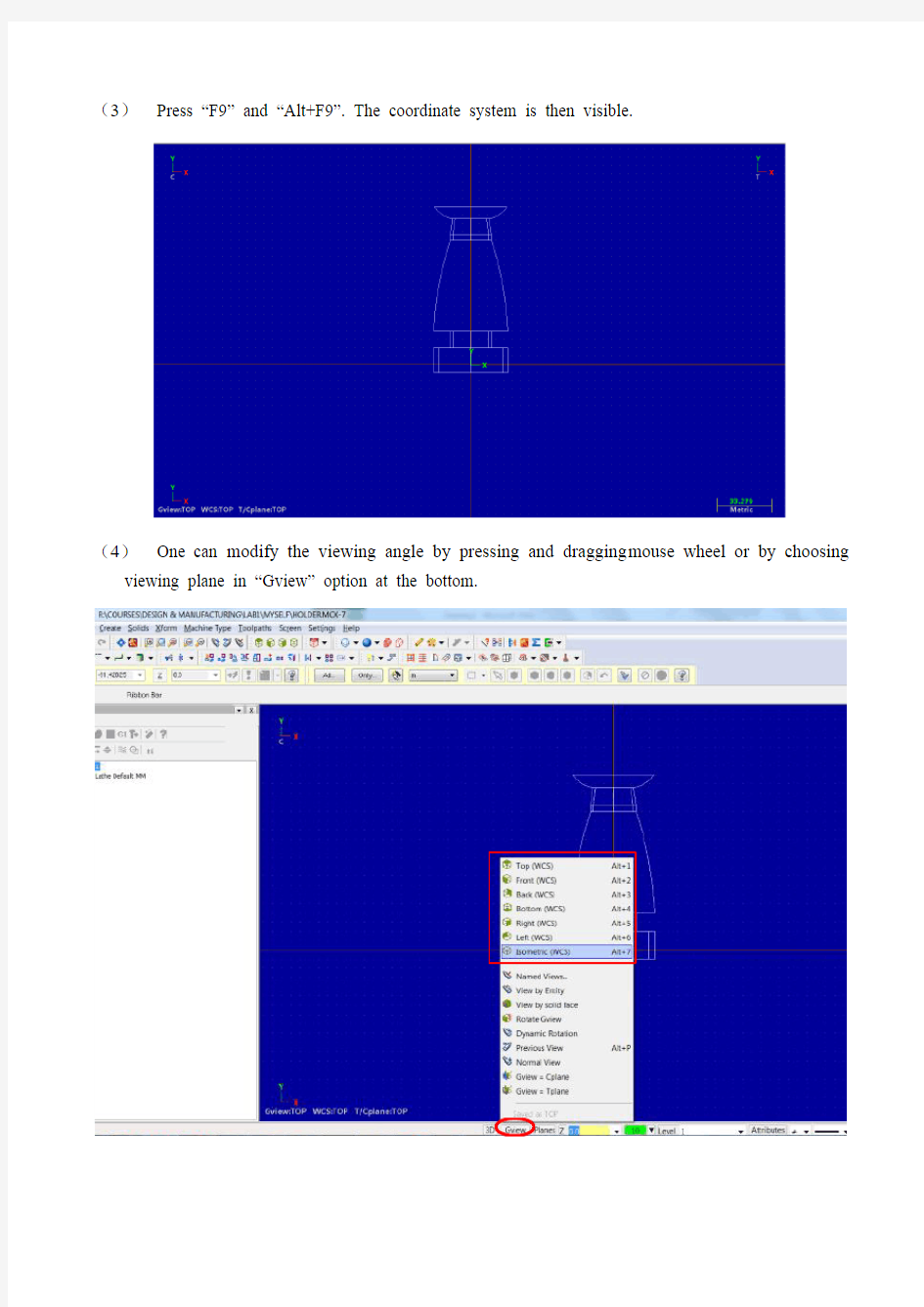
(3)Press “F9” and “Alt+F9”. The coordinate system is then visible.
(4)One can modify the viewing angle by pressing and dragging mouse wheel or by choosing viewing plane in “Gview” option at the bottom.
1.2Modify the coordinate system
(1)Click “Planes→Lathe diameter→+D +Z (WCS)”.
(2)Click “Gview→Top(WCS)” and “WCS→Top WCS”.
1.3Rotate and translate the entity as required
(1)Select the whole entity, click “Xform Move to Origin” and then select the outside circle of the top of the candle holder. Then the center of the top circle of the holder is set to be the origin.
(2)Set back to a Top Gview. Select the entity. Use the “Xform Rotate” tool to fix the center line of the entity on the x axis of the World Coordinate System which is indicated in the drawing area.
In our case, the rotate angle is -90 degree.
Then a standard view of the entity and coordinate system should be gotten.
II.Turn the wireframe into profile
2.1Set up another geometry level
(1)Click “Level” in the bottom of the software.
(2)Type “2” in the yellow input bar under “Number” in the “Main Level” section. Then click the green OK button. A new level 2 is created.
2.2Turn wireframe to profile on level 2
Click “Main Menu→Create→Turn Profile”, select the entity and press “ENTER” on the key board. Click the green OK button on the new window. The profile of the entity is created. A better vision can be achieved by hiding level1.
2.3Hide level 1
Click the “level” button in the bottom of the software. Click the two areas shown in the below with the indicated sequence. Then the “Visible” sign of level 1 is unchecked. Level 1 is hidden.
III.Plan the toolpaths
3.1Set up a machine group.
Click “Main Menu→Lathe→Default”. A machine group is then set up in the Operation Manager.
3.2Set the parameters of stock and chunk jaws
(1)Click “Tool settings” in the Operations Manager to open the “Machine Group Properties”
setting window. Then set the parameters as shown in the figures.
(2)Click “Properties” button of Stock and Chunk Jaws. Set the parameter as shown below.
3.3Plan the toolpath for facing
(1)Click “Main Mune→Toolpaths→Face”. Click the green OK button. A setting window is shown. Set the parameters in the window as shown. Turn on the flood cooling in “Coolant” option.
Left click the tool “R0.8 OD ROUGH RIGHT –80 DEG.”, right click it, choose “Edit tool”. Select “triangle” in the Shape section. Click green OK button.
(2) Click “Face parameters” tab, set the parameters shown below. Then click “Lead in/Out”. Set the parameters as shown. Click green OK button. The facing toolpath is then finished.
3.4Plan the roughing toolpaths
(1)Add two short lines on the profile as shown to avoid roughing process going into the grooving part and to leave some place for cutting off at the bottom.
(2)Click “Main Menu→Toolpaths→Rough”. A chain selecting window is shown. Select the lines along the roughing surface line by line to select the chain.
(3)Set the parameters as shown in the figure. Turn on the flood cooling in “coolant” option. Click the green OK button after setting. Then the roughing toolpath is generated.
3.5Plan the grooving toolpaths
(1)Click “Main Menu→Toolpaths→Groove”. Select “Chain” in the following “Grooving Options” window. Then a chain selecting window is shown. Select the lines along the surface of the design till the deep groove which will be made later for safety concerns. Click the green OK button when finishing the selection.
(2)Select an “OD CUTOFF RIGHT” tool and set the parameters in Toolpath parameters” tab of “Lathe Groove (Chain) Properties” windows as shown below. Then right click on the tool icon, click “Edit tool” and set the parameters as shown.
(3)Click the “Groove rough parameters” tab on the “Lathe Groove (Chain) Properties” window and set the parameters there as shown. Check the choosing boxed of “Peck Groove” and “Depth Cuts…” and set the parameters inside as shown.
(4)Click the “Groove finish parameters” tab on the “Lathe Groove (Chain) Properties” window and uncheck “Finish” on the left top corner.
3.6Plan the finishing toolpaths
(1)Click “Main Menu→Toolpaths→Finish” to set up a right-hand finishing toolpath. Choose the
same chain as that in 3.4 (2). Set the parameters as shown below. Turn on the flood cooling in “coolant” option. Click all the green OK button after setting. A right-hand finishing toolpath is set.
(2)Click “Main Menu→Toolpaths→Finish” to set up a left-hand finishing toolpath. The chosen chain is only the part which cannot be finished by the right-hand finishing as shown below.
(3)Set the parameters as shown below. T urn on the flood cooling in “coolant” option. Click all the green OK button after setting. A right-hand finishing toolpath is set.
3.7Plan the Grooving path
(1)Click “Main Menu→Toolpaths→Groove” to start a grooving toolpath setting. Choose “3 lines”
option to set the path in our case. The path is then chose as shown below. Press “ENTER” on the keyboard. Then the parameter setting window shows up.
(2)Choose the same grooving tool as in 3.5 and set the toolpath parameters as shown. Set the flood coolant. Then right click the tool, click “Edit Tool”. Set the parameters of “Inserts”, then the “Holders”. Click green OK button. Choose the “Groove rough parameters” and “Groove finish parameters” tap separately in the Lathe Groove parameters window and set the para meters there.
In the “Groove rough parameters”tab, remember to select “Peck Groove” and “Depth cuts…” and set the parameters inside. Click all the green OK button. The grooving path is then set.