SF2110D;中文规格书,Datasheet资料

Electrical Characteristics
Characteristic
Sym Notes Min
Typ Max Units Center Frequency f C 1305MHz Insertion Loss
IL
912dB Amplitude Ripple (p-p)fc-5 to fc+5 MHz 1, 2
0.7 2.0
dB Low Side Attenuation (266~290)3545dB
High Side Attenuation (320~344)35
50Delay Ripple (p-p)fc-5 to fc+5 MHz 1, 2, 330
100
ns
Group Delay in Passband 500
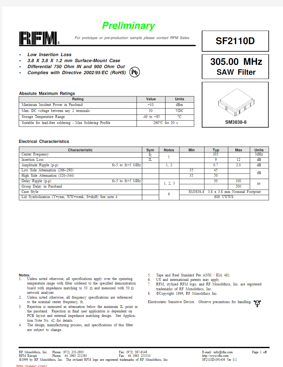
Case Style
6
SM3838-8 3.8 x 3.8 mm Nominal Footprint
Lid Symbolization (Y=year, WW=week, S=shift) See note 4
608 YWWS
?Low Insertion Loss
? 3.8 X 3.8 X 1.2 mm Surface-Mount Case ?Differential 750 Ohm IN and 900 Ohm Out ?Complies with Directive 2002/95/EC (RoHS)
Absolute Maximum Ratings
Rating
Value Units Maximum Incident Power in Passband +10dBm Max. DC voltage between any 2 terminals 30VDC Storage Temperature Range
-40 to +85
°C
Suitable for lead-free soldering - Max Soldering Profile
260°C for 30 s
305.00 MHz
SAW Filter
SF2110D Pb
Notes:1.Unless noted otherwise, all specifications apply over the operating temperature range with filter soldered to the specified demonstration board with impedance matching to 50 ? and measured with 50 ? network analyzer.2.Unless noted otherwise, all frequency specifications are referenced
to the nominal center frequency, fc.3.Rejection is measured as attenuation below the minimum IL point in
the passband. Rejection in final user application is dependent on PCB layout and external impedance matching design. See Applica-tion Note No. 42 for details.
4.The design, manufacturing process, and specifications of this filter
are subject to change.
5.Tape and Reel Standard Per ANSI / EIA 481.
https://www.wendangku.net/doc/b217031999.html, and international patents may apply.
7.RFM, stylized RFM logo, and RF Monolithics, Inc. are registered trademarks of RF Monolithics, Inc.8.?Copyright 1999, RF Monolithics Inc.
I. Differential Matching
SF2110D Demo
PCB=400-1724-001 4 port
J1-J4=500-1279-001 SMACONN L1-L2=500-1282-470 47nH 0402 L3=500-1282-560 56nH 0402
C1=501-0857-047 4.7pF 0402
C2=501-0857-180 18pF 0402
C3=501-0857-220 22pF 0402
II. Single End Matching
8-Terminal Ceramic Surface-Mount Case
3.8 X 3.8 mm Nominal Footprint
SM3838-8 Case
TOP VIEW BOTTOM VIEW
Electrical Connections
Connection
Terminals
Port 1Differential Input 1, 2Port 2Differential Output
5, 6Ground
All Others Single Ended Operation Return is Ground Differential Operation Return is Hot
Dot Indicates Pin 1
Materials
Solder Pad Termination Au plating 30 - 60 uInches (76.2-152 uM) over 80-200 uInches (203-508 uM) Ni.
Lid Fe-Ni-Co Alloy Electroless Nickel Plate (8-11% Phos-phorus) 100-200 uInches Thick Body Al 2O 3 Ceramic
Pb Free
Case Dimensions
Dimension
mm Inches Min Nom Max Min Nom Max A 3.6 3.8 4.00.1420.1500.157B 3.6 3.8 4.00.1420.1500.157C 1.05 1.20 1.350.0410.0470.053D 0.95 1.10 1.250.0370.0430.049E 0.90 1.00 1.100.0350.0400.043F 0.500.600.700.0200.0240.028G 2.39 2.54 2.690.0900.1000.110H
1.40
1.75
2.05
0.055
0.069
0.080
Tape and Reel Specifications
“B “
Nominal Size Quantity Per Reel
Inches millimeters
7178500
133303000
COMPONENT ORIENTATION and DIMENSIONS
Carrier Tape Dimensions
Ao 4.25 mm
Bo 4.25 mm
Ko 1.6 mm
Pitch8.0 mm
W12.0 mm
分销商库存信息: RFM
SF2110D